Do you have a question about the Pioneer SA-9900 and is the answer not in the manual?
Lists semiconductor types and quantities used in the unit.
Details output power, distortion, and frequency response.
Describes equalizer and control amplifier characteristics.
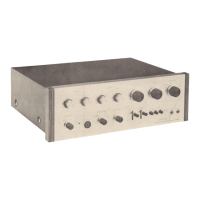
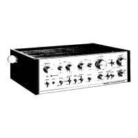
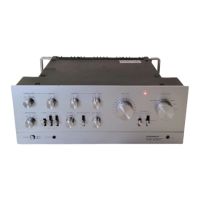
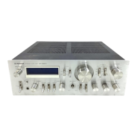
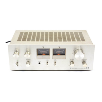
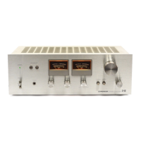
Controls for speaker selection, headphone output, and balance.
Power switch, volume, function selector, and mode switches.
Bass, treble, tone, filter, and attenuator adjustments.
Pilot lamp status indicator.
Details AC outlet usage and speaker system wiring.
Explains PRE/POWER AMP switch and input/output jacks.
Illustrates input, control, and switching circuit blocks.
Shows power amplifier, power supply, and protection circuit blocks.
Explains input impedance and sensitivity adjustments.
Describes muting, overload, and overheating protection features.
Important warnings and guidelines for safe disassembly.
Steps for removing exterior panels and the front panel.
Steps to remove power amplifier and protection circuit boards.
Instructions for removing power supply, control, tone, and switch circuits.
Steps to remove input, fuse boards, and pilot lamps.
Labels and identifies components from the top view.
Labels and identifies components from the bottom view.
Steps to prepare the unit for calibration.
Procedures for setting idle current and testing protection circuit.
Lists and visually identifies major external parts.
Lists internal parts like switches, knobs, and circuit boards.
Lists chassis parts, fasteners, electrical components, and assemblies.
Detailed exploded view of the power amplifier assembly.
Provides the complete circuit schematic of the amplifier.
Lists capacitors and resistors with specifications and part numbers.
Detailed schematic for the input circuit.
Lists components for the input circuit assembly.
Detailed schematic for the control amplifier.
Lists components for the control amplifier assembly.
Detailed schematic for the power amplifier.
Lists components for the power amplifier assembly.
Detailed schematic for the protection circuit.
Schematic and component list for the fuse board.
Schematic and component list for power supply circuit 1.
Schematic and component list for power supply circuit 2.
Schematic and component list for power supply circuit 3.
Detailed schematic for the volume control circuit.
Detailed schematic for the tone switch circuit.
Lists components for the tone switch circuit assembly.
Detailed schematic for the switch circuit assembly.
Lists components for the switch circuit assembly.
Details internal pads, cloth cover, and packing case.
| Frequency Response | 5Hz to 100kHz |
|---|---|
| Total Harmonic Distortion | 0.1% |
| Damping Factor | 50 |
| Input Sensitivity | 2.5mV (MM), 150mV (line) |
| Signal to Noise Ratio | 90dB (line) |
| Output | headphone jack |
| Type | Integrated Amplifier |
| Channel Separation | 60dB |