Do you have a question about the Pioneer SA-9500II and is the answer not in the manual?
Controls power ON/OFF and rear panel switched outlets.
Bypasses tone controls for flat frequency response.
Adjusts low frequencies with two turnover points.
Adjusts high frequencies with two turnover points.
For connecting stereo headphones.
Selects speaker system operation (OFF, A, B, A+B).
Reduces low-frequency noise below 15Hz.
Reduces high-frequency noise above 8kHz.
Adjusts stereo balance between left and right channels.
Adjusts speaker and headphone volume.
Selects phono input resistance and capacitance.
Selects desired playback program source.
For tape playback or monitoring recording.
For duplicating tapes between two decks.
Reduces volume by 20dB temporarily.
Enhances low and high frequencies at low volumes.
Selects stereo reproduction modes.
Explains the circuit for phono signal amplification and RIAA equalization.
Details the NFB type tone control circuits for bass and treble.
Describes midrange, low, and high frequency tone control operation.
Bypasses the tone control circuit.
Details the circuit of the power amplifier stage.
Describes the circuit protecting transistors and speakers.
Explains the circuit driving the relay for protection and muting.
How detector circuits trigger the relay drive.
Details the power supply circuit for various sections.
Circuit activated by load impedance issues.
Detects DC potential at the power amplifier junction.
Instructions for removing the top cover.
Instructions for removing the front panel components.
Instructions for removing the bottom plate.
Instructions for removing the control amplifier.
Instructions for removing the left power amplifier block.
Instructions for removing the right power amplifier block.
Instructions for removing a switch assembly.
Instructions for removing the equalizer amplifier assembly.
Instructions for removing another switch assembly.
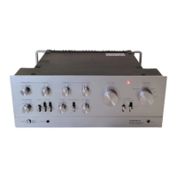
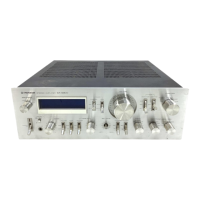
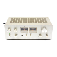
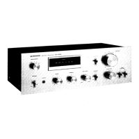
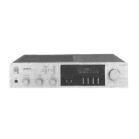
Identifies components on the front panel.
Identifies components with the front panel removed.
Identifies components from the top view.
Identifies components from the bottom view.
Identifies components from the rear view.
Lists symbols and descriptions for hardware.
Lists miscellaneous components like semiconductors and capacitors.
Presents the main circuit schematic.
Details the switch assembly AWS-109.
Details the phono jack assembly AWX-107.
Details the equalizer amplifier assembly AWF-024.
Details the switch assembly AWS-102.
Details the control amplifier assembly AWG-045.
Details the power amplifier assembly AWH-052.