Do you have a question about the Pioneer SA-706 and is the answer not in the manual?
Lists ICs, Transistors, and Diodes used in the amplifier.
Details circuitry, power output, distortion, input/output specs.
Specifies speaker impedance, damping factor, and input/output levels.
Outlines bass and treble control ranges and frequencies.
Covers power requirements, consumption, dimensions, weight.
Lists items included with the amplifier, like operating instructions.
Illustrates how to connect audio sources and speakers to the amplifier.
Details the grounding procedure for safety and noise reduction.
Explains the function and use of the interference filter switch.
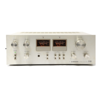
Describes power meters, peak indicators, and their functions.
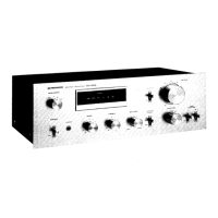
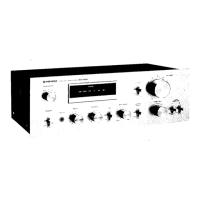
Details volume, function, and balance controls on the front panel.
Explains the operation of power, speaker, loudness, and tape switches.
Location for connecting headphones.
Details the phono input circuit, including interference filter.
Explains the design and operation of the power amplifier stage.
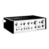
Instructions for removing the top cover and side panels.
Steps for removing the bottom plate.
Procedure for disassembling the front panel components.
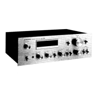
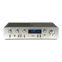
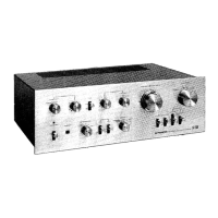
Identifies parts visible on the front panel.
Identifies internal components accessible after panel removal.
Procedure for adjusting the idle current of the amplifier.
Steps to calibrate the output power meters.
Detailed schematic of the amplifier's circuitry.
Compares miscellaneous parts between SA-7700/KU and SA-7700/KC.
Notes on AF assembly differences for KC model.
Notes on Tone & Indicator assembly differences for KC model.
Notes on Terminal assembly differences for KC model.
Notes on VR assembly differences for KC model.
Notes on RFI Switch assembly differences for KC model.
Specifications for SA-706, noting differences from SA-7700.
Power requirements, dimensions, weight for SA-706 models.
Part number differences for switches across SA-706 variants.
Part number differences for capacitors across SA-706 variants.
Part number differences for PC board assemblies across SA-706 variants.
Part number differences for fuses across SA-706 variants.
Identifies rear panel components specific to SA-706/HG.
Notes on AF Assembly (GWK-112) differences for SA-706/S, S/G.
Notes on Tone & Indicator Assembly (GWX-163) for SA-706/S, S/G.
Notes on Terminal Assembly (GWX-161) for SA-706/S, S/G.
Notes on VR Assembly (GWX-160) for SA-706/S, S/G.
Notes on RFI Switch Assembly (GWX-162) for SA-706/S, S/G.
Details for the DIN Connector Assembly (AWX-137).
Circuitry notes for AF Assembly (GWK-115) for SA-706/S, S/G.
Circuitry notes for Tone & Indicator Assembly (GWX-173) for SA-706/S, S/G.
Circuitry notes for Terminal Assembly (GWX-171) for SA-706/S, S/G.
Circuitry notes for VR Assembly (GWX-170) for SA-706/S, S/G.
Circuitry notes for RFI Switch Assembly (GWX-172) for SA-706/S, S/G.
| Damping Factor | 40 |
|---|---|
| Input Sensitivity | 2.5mV (MM), 150mV (line) |
| Speaker Load Impedance | 4Ω to 16Ω |
| Total Harmonic Distortion | 0.05% |
| Dimensions | 420 x 150 x 369mm |
| Semiconductors | 36 x transistors |
| Channel Separation | 65dB (line) |