EasyManua.ls Logo

Pioneer SA-750 Service Manual

Pioneer SA-750
25 pages
To Next Page IconTo Next Page
Page #1 background imageLoading...
Page #1 background image
@)
PIONEER’
Service
PAL
ETIIET
CIRCUIT
DESCRIPTIONS
REPAIR
&
ADJUSTMENTS
ORDER
NO.
ARP-485-0
STEREO
AMPLIFIER
MODEL
SA-750
COMES
IN
SIX
VERSIONS
DISTINGUISHED
AS
FOLLOWS:
Type
Voltage
Remarks
KU
AC120V
only
U.S.A.
model
KC
AC120V
only
Canada
model
HE
AC220V,
240V
(switchable)
European
continent
model
Ss
AC110V,
120V,
220V,
240V
(switchable)
General
export
model
7
YP
AC240V
only
Australia
model
HEZ
AC220V,
240V
(switchable)
West
Germany
model
e
This
service
manual
is
applicable
to
the
KU
type.
For
servicing
of
the
KC,
HE,
HEZ,
S,
and
YP
types,
please
refer
to
pp.
24~28.
e
Ce
manuel
d’instruction
se
refére
au
mode
de
réglage,
in
francais.
e
Este
manuel
de
servicio
trata
del
método
de
ajuste
escrito
en
espajfiol.
1.
SPECIFICATIONS
...............---..
2
10.
ADJUSTMENTS
.....................
21
2.
FRONT
PANEL
FACILITIES.............
3
REGUAGE
oad
ane
SE
ae
Re
22
3.
PARTS
LOCATION
...............004.
5
ASUSTE
2
vi
i
ee
eh
eee
rs
BOR
RS
23
4.
EXPLODEDVIEW....................
7
11.
SAFETY
INFORMATION
...............
24
5.
BLOCK
DIAGRAM
...................
9
12...
JFORIKG-TYPE
ws
o.an:
Be.
wogau
bi
ated
ee
24
6.
P.C.
BOARDS
CONNECTION
DIAGRAM
....
11
13.
FORHETYPE
..................000,
25
7.
SCHEMATIC
DIAGRAM
................
15
14.
FOR
HEZ
TYPE.....................
26
8.
ELECTRICAL
PARTS
LIST..............
18
195.
(ROR:S
TY
PEs
cca
Bathe
eats
c
aes
31
9.:
PACKING
4
{233250
t
Betis
She
acess
eed
20
16.
FORYPTYPE..............
00.0000
32
PIONEER
ELECTRONIC
CORPORATION
4-1,
Meguro
1-Chome,
Meguro-ku,
Tokyo
153,
Japan
PIONEER
ELECTRONICS
(USA)
INC.
P.O.
Box
1760,
Long
Beach,
California
90801
U.S.A.
TEL:
(80O}
421-1404,
(213)
420-5914
PIONEER
ELECTRONIC
[EUROPE]
N.V.
Keetbergiaan
1,
2740
Beveren,
Belgium
TEL:
03/775:28:08
PIONEER
ELECTRONICS
AUSTRALIA
PTY.LTO.
178-184
Boundary
Road,
Braeside,
Victoria
3195,
Australia
TEL:
(O93)
580-9911
YA
©
MAR.
1984
Printed
in
Japan
Question and Answer IconNeed help?

Do you have a question about the Pioneer SA-750 and is the answer not in the manual?

Pioneer SA-750 Specifications

General IconGeneral
BrandPioneer
ModelSA-750
CategoryAmplifier
LanguageEnglish

Summary

1. Specifications

Amplifier Specifications

Details continuous power, THD, damping factor, input sensitivity, output level, and frequency response.

Miscellaneous Unit Specifications

Covers power requirements, consumption, dimensions, and weight of the unit.

Included Parts and Operating Notes

Lists items included with the unit and provides general operating guidance.

2. Front Panel Facilities

Front Panel Switches and Indicators

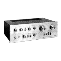
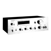
Details the operation of power, loudness, input selection, and indicator lights on the front panel.

Front Panel Audio Controls

Explains the function and adjustment of Bass, Treble, Balance, and Volume controls.

Speaker and Headphone Connectivity

Describes speaker selection switches and the headphone jack for audio output.

3. Parts Location

Component Identification and Layout

Illustrates and labels the location of major internal and external components.

4. Exploded View and Parts Identification

Exploded View Diagram

Provides a visual breakdown of the unit's assembly for parts identification.

Component Part Numbers and Notes

Lists components with part numbers and important notes for replacement.

5. Block Diagram

Audio Signal Path Diagram

Illustrates the overall signal path through the amplifier's audio stages.

6. P.C. Board Connection Diagram

Printed Circuit Board Wiring

Shows the internal wiring connections between different circuit boards.

7. Schematic Diagram

Detailed Electronic Circuit Schematics

Presents the complete electronic circuit diagrams for all sections of the amplifier.

Circuit Diagram Notes and Symbols

Explains component notations, signal routes, adjustment points, and general schematic symbols.

8. Electrical Parts List

Comprehensive Component Part Listings

Detailed list of all electrical components with their part numbers and symbols.

9. Packing

Packing Contents and Materials

Lists items included in the product packaging and their respective part numbers.

10. Adjustments

Idle Current Adjustment Procedure

Step-by-step guide to perform the idle current adjustment for optimal performance.

11. Safety Information

General Safety Precautions and Checks

Outlines essential safety checks, including leakage current testing, for user and technician protection.

Product Safety Notice and Component Guidance

Warns about special safety characteristics of components and the use of recommended replacements.

12. For KC Type

KC Type Specific Information

Details miscellaneous parts differences and schematic for the KC type.

13. For HE Type

HE Type Specific Information

Outlines miscellaneous parts differences and line voltage selection for the HE type.

14. For HEZ Type

HEZ Type Specific Information

Lists miscellaneous parts differences and line voltage selection for the HEZ type.

15. For S Type

S Type Specific Information

Details miscellaneous parts differences for the S type.

16. For YP Type

YP Type Specific Information

Identifies miscellaneous parts differences for the YP type.

Related product manuals