Do you have a question about the Pioneer SA-7700 and is the answer not in the manual?
Lists semiconductor components used in the amplifier.
Details the amplifier's technical performance and audio characteristics.
Specifies electrical requirements, physical size, and weight of the unit.
Lists items included with the product.
Covers Loudness Contour and Hum/Noise specifications.
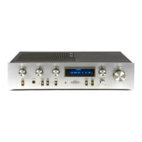
Explains primary controls for audio adjustment and source selection.
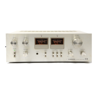
Describes visual output level and clipping indicators.
Details power supply and speaker output selection features.
Explains the phono preamplifier and its interference filter.
Details the design of the main audio amplification stage.
Describes the circuit that drives the power output meters.
Explains the circuit for the peak clipping indicator LED.
Details the circuit protecting speakers and amplifier from faults.
Explains the power supply system providing voltages to the unit.
Instructions for removing the top enclosure panels.
Steps for accessing the unit from the bottom.
Procedure for removing the front control panel.
Procedures for removing heat sink and replacing meter lamp.
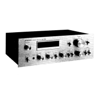
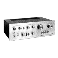
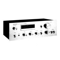
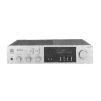
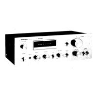
Identifies components visible on the front panel.
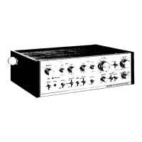
Identifies internal components from top and rear views.
Procedure for setting the amplifier's quiescent current.
Procedure for calibrating the power output meters.
The complete circuit diagram for the amplifier.
Lists various components and their part numbers.
Diagrams and lists for Terminal, AF, Tone, RFI, and VR assemblies.
| Power Output | 40 watts per channel into 8Ω (stereo) |
|---|---|
| Total Harmonic Distortion | 0.1% |
| Frequency Response | 10 Hz to 50 kHz |
| Damping Factor | 30 |
| Input Sensitivity | 2.5mV (MM), 150mV (line) |
| Channel Separation | 50dB (MM), 55dB (line) |
| Dimensions | 430 x 138 x 341mm |
| Weight | 10.3kg |
| Speaker load impedance | 4Ω to 16Ω |
| Type | Stereo Integrated Amplifier |
| Semiconductors | 18 x diodes |