EasyManua.ls Logo

Pioneer SA-950 Service Manual

Pioneer SA-950
28 pages
To Next Page IconTo Next Page
Page #1 background imageLoading...
Page #1 background image
9
SAARC
went
ADDITIONAL
QW)
PIONEER’
|
WY
svi
ia
(ere
anual
SeoERNG
ARP-494-0
STEREO
AMPLIFIER
SA-950
MODEL
SA-950
COMES
IN
SEVEN
VERSIONS
DISTINGUISHED
AS
FOLLOWS:
Voltage
Remarks
AC220V,
240V
(switchable)
European
continent
model
AC
120V
only
U.S.A.
model
AC120V
only
Canada
model
AC110V,
120V,
220V,
240V
(switchable)
General
export
model
AC110V,
120V,
220V,
240V
(switchable)
U.S.
Military
model
AC240V
only
Australia
model
AC220V,
240V
(switchable)
West
Germany
model
e
The
basic
performance
of
the
model
SA-950
is
the
same
as
the
model
SA-940.
Please
refer
to
the
SA-
940/KU
service
manual
(ARP-298-0)
with
the
exception
of
this
service
manual.
¢
The
model
SA-950
differs
from
the
model
$A-940
in
style
(color).
PIONEER
ELECTRONIC
CORPORATION
<--1.
Meguro
1-Chome,
Meguro-ku,
Tokyo
153,
Japan
PIONEER
ELECTRONICS
[USA]
INC.
P.O.
Box
1760,
Long
Beach,
California
30801
U.S.A.
TEL:
(B00)
421-1404,
[213]
420-5914
PIONEER
ELECTRONIC
[EUROPE]
N.V.
Keetberglaan
1,
2740
Beveren,
Belgium
TEL:
03/775-28:08
PIONEER
ELECTRONICS
AUSTRALIA
PTY.
LTD.
178-184
Boundary
Road,
Braeside,
Victoria
3195,
Australia
TEL:
(O39)
580-9911
YL
©
JAN.
1984
Printedgn
Japan
Question and Answer IconNeed help?

Do you have a question about the Pioneer SA-950 and is the answer not in the manual?

Pioneer SA-950 Specifications

General IconGeneral
Power Output80 watts per channel into 8Ω (stereo)
Frequency Response5Hz to 100kHz
Input Impedance50kΩ (line)
Dimensions420 x 150 x 360 mm (W x H x D)
Damping factor50
Input sensitivity2.5mV (MM), 150mV (line)
Speaker load impedance4Ω to 16Ω

Summary

1. SPECIFICATIONS

Amplifier Section

Details the audio performance characteristics of the amplifier, including power output and frequency response.

2. FRONT PANEL FACILITIES

Front Panel Controls and Indicators

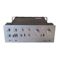
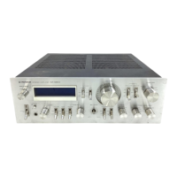
Explains the function of each button, knob, switch, and indicator on the front of the unit.

3. PARTS LOCATION

4. EXPLODED VIEWS AND PARTS LIST

7. SCHEMATIC DIAGRAM

Circuit Schematics and Component Details

Offers detailed electrical schematics and identifies specific components used in the circuits.

8. ELECTRICAL PARTS LIST

Component Identification and Part Numbers

A comprehensive list of all electrical parts, including their part numbers and descriptions.

10. ADJUSTMENTS

Idle Current Adjustment Procedure

Step-by-step instructions for correctly adjusting the idle current of the amplifier's output stage.

11. SAFETY INFORMATION

Safety Precautions and Notices

Crucial safety warnings, checks, and notices for technicians and users to prevent hazards.

Related product manuals