Do you have a question about the Pioneer VSX-1016V-S and is the answer not in the manual?
Checkpoints for continued protection of customer and service technician.
Measure leakage current to earth ground. Must not exceed 0.5 mA.
Special safety characteristics of electrical/mechanical parts. Use specified replacement parts.
Conform to regulations, maintain safe servicing environment, use specified parts, no modifications.
Ensure optimum performance and characteristics within specification.
Use specified and equivalent lubricants, adhesives, and parts.
Proper cleaning of parts like optical pickups, heads, lenses for performance restoration.
Set shipping mode or install shipping screws to protect products from damage during transit.
Power output specifications for stereo and multichannel modes.
Input sensitivity, frequency response, tone control, and signal-to-noise ratio specifications.
Video input/output specifications, signal-to-noise ratio, and frequency response.
FM and AM tuner specifications including frequency range and sensitivity.
Power output and distortion specifications for various amplifier models.
Power requirements, consumption, dimensions, weight, and furnished parts.
Exploded view and parts list for the packing section.
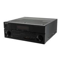
Exploded view of the exterior parts of the unit.
Exploded view of the chassis components.
Exploded view of the rear panel connectors and components.
Exploded view of the power amplifier section components.
Exploded view of the front panel components.
Block diagram showing the audio signal flow and main circuit blocks.
Block diagram showing the video signal flow and main circuit blocks.
Diagram showing the overall wiring connections between various assemblies.
Schematic diagram for the Audio In Assy (part 1 of 2).
Schematic diagrams for Audio In Assy (part 2) and 12V-Reg Assy.
Schematic diagram for the Main Control Assy (part 1 of 2).
Schematic diagrams for Main Control (part 2), Guard-C, F, and R Assys.
Schematic diagram for the DSP Assy (part 1 of 2) for VSX-1016V.
Schematic diagram for the DSP Assy (part 2 of 2) for VSX-1016V.
Schematic diagram for the DSP Assy (part 1 of 2) for VSX-1016TXV and VSX-80TXV.
Schematic diagram for the DSP Assy (part 2 of 2) for VSX-1016TXV and VSX-80TXV.
Schematic diagram for the Composite Assy.
Schematic diagrams for S-Video and Bridge 2 Assys.
Schematic diagram for the Component Assy.
Schematic diagrams for Display, Volume, and Multi Jog Assys.
Schematic diagrams for Headphone, Front-In, Primary, and Trans 1 Assys.
Schematic diagrams for Trans 2-1, Diode 1, VH TR, and PS/SP Assys.
Schematic diagrams for Trans 2-2, Trans Side, Local P-Supply, DC/DC, IR I/O, and Video Connect Assys.
Schematic diagrams for Power Amp-L, Posit1-L, and Posit2-L Assys.
Schematic diagrams for Power Amp-R and Posit1-R Assys.
Schematic diagrams for Bridge 1-L, Power Amp In, and Power Protect Assys.
Schematic diagram for the HDMI & DVC Assy.
Schematic diagram for the USB Assy (VSX-1016V only).
Visual representation of the location of various PCB assemblies within the unit.
Comprehensive list of all PCB assemblies used in the product, with part numbers.
Indicates that there is no specific adjustment procedure information available in this section.
Information regarding diagnosis procedures, including test modes and error indications.
Procedure to enter and exit test mode for checking system versions.
Information on how to view detected protection processes such as DC detection and overload.
Displays error messages for amplifier abnormalities like AMP ERROR, FAN STOP, and OVERHEAT.
Details protection circuit processes for DC detection, overload, overheat, and trigger failure.
Flowchart for troubleshooting issues related to DSP Assy.
Simple diagnosis and troubleshooting steps for HDMI connection issues.
Error indications and operations for USB module issues like overcurrent or unsupported media.
Procedure for updating the USB module firmware using a USB memory stick.
Instructions for disassembling the unit, specifically the Power Amp Block.
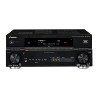
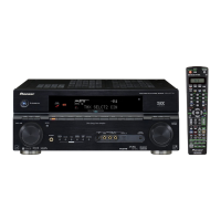
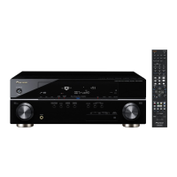
Explanation of the front panel controls and indicators.
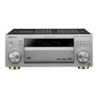
Explanation of the front panel controls and indicators specific to this model.
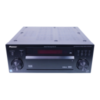
Explanation of the front panel controls and indicators for these models.
| Channels | 7.1 |
|---|---|
| HDMI Inputs | 2 |
| HDMI Outputs | 1 |
| Input Sensitivity | 200 mV |
| Digital Audio Inputs | Optical: 3, Coaxial: 2 |
| Phono Input | Yes |
| Remote Control | Yes |
| Speaker Impedance | 6-16 Ohms |
| Audio Formats Supported | Dolby Digital, DTS |
| Multi-Zone Capability | Yes (Zone 2) |
| Frequency Response | 5 Hz - 100 kHz |
| Video Inputs/Outputs | Component: 3 in / 1 out, Composite: 5 in |
| Analog Audio Inputs/Outputs | 5 RCA Inputs, 2 RCA Outputs |
| Multi-room Output | Yes (Zone 2) |
| Input Sensitivity/Impedance | 200 mV / 47 kΩ |