EasyManua.ls Logo

Pioneer VSX 108 - AV Receiver User Manual

Pioneer VSX 108 - AV Receiver
39 pages
To Next Page IconTo Next Page
Page #1 background imageLoading...
Page #1 background image
ORDER NO.
PIONEER CORPORATION 4-1, Meguro 1-chome, Meguro-ku, Tokyo 153-8654, Japan
PIONEER ELECTRONICS SERVICE, INC. P.O. Box 1760, Long Beach, CA 90801-1760, U.S.A.
PIONEER ELECTRONIC (EUROPE) N.V. Haven 1087, Keetberglaan 1, 9120 Melsele, Belgium
PIONEER ELECTRONICS ASIACENTRE PTE. LTD. 253 Alexandra Road, #04-01, Singapore 159936
PIONEER CORPORATION 1999
c
VSX-108
RRV2146
T – IZE OCT. 1999 Printed in Japan
Type
Model
Power Requirement Remarks
VSX-108
KUXCN AC120V
THIS MANUAL IS APPLICABLE TO THE FOLLOWING MODEL(S) AND TYPE(S).
AUDIO MULTI - CHANNEL RECEIVER
1. SAFETY INFORMATION
......................................
2
2. EXPLODED VIEWS AND PARTS LIST
...............
3
3. BLOCK DIAGRAM AND SCHEMATIC DIAGRAM
.....
6
4. PCB CONNECTION DIAGRAM
.........................
17
5. PCB PARTS LIST
...............................................
22
6. ADJUSTMENT
....................................................
24
CONTENTS
7. GENERAL INFORMATION
................................
26
7.1 PARTS
..........................................................
26
7.1.1 IC
............................................................
26
7.1.2 DISPLAY
.................................................
33
8. PANEL FACILITIES AND SPECIFICATIONS
.......
35
Question and Answer IconNeed help?

Do you have a question about the Pioneer VSX 108 - AV Receiver and is the answer not in the manual?

Pioneer VSX 108 - AV Receiver Specifications

General IconGeneral
THD0.08 %
Power Output (8 ohms, 20Hz-20kHz, 0.08% THD)80 W
Phono InputYes
Video Formats SupportedComposite
Input Sensitivity200 mV
Video ConnectionsComposite
Amplifier TypeDiscrete
Digital Inputs (Specific)2 optical, 1 coaxial
Auto CalibrationYes

Summary

1. SAFETY INFORMATION

1. SAFETY PRECAUTIONS

Guidelines for customer and technician safety checks and precautions.

LEAKAGE CURRENT CHECK

Procedure to measure AC leakage current to earth ground.

2. PRODUCT SAFETY NOTICE

Important information regarding safety-related replacement parts and hazards.

2. EXPLODED VIEWS AND PARTS LIST

2.1 PACKING

Details the components included in the product packaging.

2.2 EXTERIOR

EXTERIOR PARTS LIST

Lists external components with their part numbers and visual representation.

3. BLOCK DIAGRAM AND SCHEMATIC DIAGRAM

3.1 BLOCK DIAGRAM, OVERALL WIRING DIAGRAM, AC O/P, AC I/P and PW SW PCBS

Overview of the receiver's block and wiring diagrams for specific PCBs.

3.2 TUNER PCB

Detailed schematic diagram for the Tuner PCB.

3.3 MAIN PCB (1/2)

Schematic diagram for the Main PCB, Part 1.

3.4 MAIN (2/2) and PHONE PCBS

Schematic diagrams for the Main PCB (Part 2) and Phone PCB.

3.5 DISPLAY PCB

Schematic diagram for the Display PCB.

4. PCB CONNECTION DIAGRAM

4.1 TUNER PCB CONNECTION DIAGRAM

Component layout and connection diagram for the Tuner PCB.

4.2 MAIN and PHONE PCBS CONNECTION DIAGRAMS

Component layout and connection diagrams for Main and Phone PCBs.

4.3 AC O/P, AC I/P, PW SW and DISPLAY PCBS CONNECTION DIAGRAMS

Component layout diagrams for AC O/P, AC I/P, PW SW, and Display PCBs.

5. PCB PARTS LIST

LIST OF ASSEMBLIES

List of major assemblies and their part numbers.

6. ADJUSTMENT

6.1 TUNER SECTION ADJUSTMENTS

Detailed procedures for tuning AM IF, FM IF, and tracking adjustments.

7. GENERAL INFORMATION

7.1 PARTS

Information on integrated circuits (ICs) used in the receiver.

7.1.2 DISPLAY

Information on the FL Tube display, including grid assignment and pin connections.

8. PANEL FACILITIES AND SPECIFICATIONS

8.1 PANEL FACILITIES

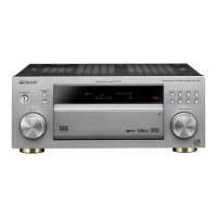
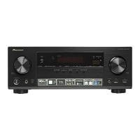
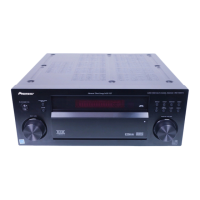
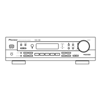
Description and identification of front panel controls and indicators.

Remote Control Unit Functions

Multi-Function and Mode Buttons

Buttons for device control, mode selection (Tuner, Pro Logic, Surround), and function settings.

Tuner and Operation Specific Buttons

Buttons for tuner operations, number/surround settings, and specific audio modes.

Volume and Tone Control Buttons

Buttons for adjusting volume, loudness, muting, and stereo playback.

8.2 SPECIFICATIONS

Audio Output and Input Specifications

Details on power output, frequency response, sensitivity, and impedance for various inputs.

Tuner Section Specifications

Specifications for FM and AM tuner frequency ranges and response.

Miscellaneous and Furnished Parts

Includes power, dimensions, weight, and list of supplied accessories.

Related product manuals