Do you have a question about the Pioneer VSX-827-K and is the answer not in the manual?
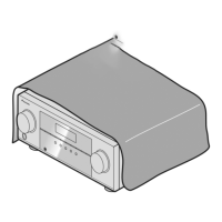
Exploded view diagram illustrating the exterior components of the AV receiver.
Comparison of part numbers and construction for the AUDIO ASSY.
Comparison of part numbers for the AMP7 ASSY, noting incompatibility.
Comparison of part numbers for the AMP5 ASSY, noting incompatibility.
Comparison of part numbers and construction for the MAIN ASSY.
This document serves as a comprehensive service manual for the Pioneer VSX-827-K AV Receiver, providing essential information for its maintenance and repair. It is designed for service technicians and should be used in conjunction with other relevant manuals, specifically the VSX-1022-K/CUXESM and VSX-822-K/CUXESM service manuals, as well as the operating instructions for detailed specifications and panel facilities.
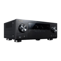
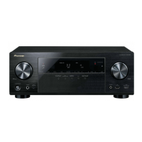
The VSX-827-K is an AV receiver, a central component in a home entertainment system, designed to receive audio and video signals from various sources, process them, and then send them to display devices (like televisions or projectors) and loudspeakers. Its primary function is to act as a hub for all your audio and video components, offering robust signal processing and amplification capabilities. The receiver supports a wide range of input sources, allowing users to connect devices such as Blu-ray players, gaming consoles, cable boxes, and streaming devices. It is engineered to deliver high-quality audio and video performance, enhancing the user's entertainment experience.
A key aspect of this service manual is the "Contrast of Miscellaneous Parts" section, which highlights the differences in components between the VSX-827-K and its related models. This is crucial for accurate part identification and ordering. For instance, parts marked with "NSP" are generally unavailable through the standard Master Spare Parts List, indicating that they might be specialized or not commonly stocked. Furthermore, components marked with a specific safety symbol denote parts critical to the safety of the device. When replacing these, it is imperative to use parts of identical designation to maintain the device's safety standards. This emphasis on safety extends to the handling of screws adjacent to these marks, which are often involved in disassembly procedures. The manual also provides guidance on the application of lubricants or glue, stressing the importance of following specific instructions where provided, or using appropriate judgment in their absence.
The manual includes detailed instructions on how to order resistors, requiring technicians to convert resistance values into a specific code form. This ensures precision in part replacement, whether dealing with two-effective-digit resistors (like 560 ohm or 47k ohm) or high-precision metal film resistors (like 5.62k ohm). This meticulous approach to part identification underscores the complexity and precision involved in servicing modern AV receivers.
The "Contrast Table" is a vital resource, outlining the specific differences in PCB assemblies and packing section components between the VSX-827-K/SYXE8 and the VSX-1022-K/CUXESM models. This table covers various PCB assemblies, including the Main, Front, Video, STBY, Audio, DMAIN, CPU, and AMP7 assemblies. Each entry lists the model number, type, power requirement (AC 220 V to 230 V for both VSX-827-K and VSX-527-K), and remarks. This level of detail is essential for technicians to ensure they are using the correct parts for the specific model being serviced. For example, the Main PCB Assembly for the VSX-827-K/SYXE8 has a different order number (7025HK1108030-IL) compared to the VSX-1022-K/CUXESM (7025HK1108010-IL), even though both are "PCB TTL ASSY MAIN." Similar distinctions are made for other assemblies, highlighting the subtle but critical differences between models.
Beyond internal components, the manual also addresses the "Packing Section," which includes items like the remote control, CD-ROM for operating instructions, and various language versions of the operating instructions in PDF format. This section also covers quick start guides, gift boxes, warranty cards, and AC power cords. These details are important for ensuring that all accessories and documentation are correctly identified and supplied.
The "Exterior Section" of the manual provides an exploded view of the device, illustrating the arrangement of external components such as the back chassis, feet, power AC socket, and various screws. This visual aid is invaluable for disassembly and reassembly, helping technicians understand the physical structure of the receiver. Specific part numbers are provided for these exterior components, along with remarks that cross-reference with "EXPLODED VIEWS" for easier navigation.
Further "Contrast of PCB Assemblies" sections delve into specific boards like the AUDIO ASSY, AMP7 ASSY, AMP5 ASSY, MAIN ASSY, CPU ASSY, VIDEO ASSY, FRONT ASSY, and STBY ASSY. These sections detail component differences, such as specific resistors, relays, connectors, and terminals. For instance, the AUDIO ASSY might have different RCA 2-pin terminals depending on the model. The MAIN ASSY section lists differences in metal film resistors, relays, and board push/screw terminals. It's explicitly stated that while some assemblies might have different part numbers, they may consist of the same service components, or conversely, be entirely incompatible despite similar functions. This distinction is crucial for preventing incorrect part substitutions.
For the VIDEO ASSY, differences in RCA 6-pin terminals are noted, and a general remark highlights that "apart from the registered parts for service described above, some nonregistered parts are also different." This implies that technicians must be vigilant and consult all available documentation to ensure complete and accurate servicing. The FRONT ASSY section details differences in specific resistors, while the STBY ASSY covers fuses, power transformers, and connectors. Again, the manual emphasizes that some assemblies, despite different part numbers, might share service components, or be entirely distinct.
In summary, this service manual is an indispensable tool for anyone involved in the maintenance and repair of the Pioneer VSX-827-K AV Receiver. It provides a meticulous breakdown of components, highlights critical differences between models, and stresses the importance of safety and precision in part replacement. Its comprehensive nature, combined with cross-referencing to other manuals and visual aids, ensures that technicians have all the necessary information to effectively service the device, thereby extending its lifespan and maintaining its high performance.
| Channels | 7.2 |
|---|---|
| HDMI Inputs | 6 |
| HDMI Outputs | 1 |
| Network Capability | Yes |
| Wi-Fi | No |
| Bluetooth | Yes |
| 3D Support | Yes |
| Audio Return Channel (ARC) | Yes |
| AirPlay | Yes |
| AV Streaming | Yes |
| Internet Radio | Yes |
| Frequency Response | 10 Hz - 100 kHz |
| Input Sensitivity/Impedance | 200 mV/47 kΩ |
| Signal-to-Noise Ratio | 98 dB |
| HDMI Version | 1.4a |
| HDCP Support | Yes |
| Network Connectivity | Ethernet |
| Multi-room Audio | No |
| Phono Input | No |
| USB Port | 1 (Front) |
| Digital Audio Inputs | 2 Optical, 1 Coaxial |
| Analog Audio Inputs | 4 |
| Power Output per Channel | 80W (8 ohms, 20Hz-20kHz, 0.08% THD, 2ch driven) |
| Audio Formats Supported | Dolby TrueHD, DTS-HD Master Audio |
| Dimensions (W x H x D) | 435 x 168 x 362.5 mm |
| Weight | 8.3 kg |
| USB Input | 1 |
| Total Harmonic Distortion | 0.08% |