Do you have a question about the Pioneer VSX-822-K and is the answer not in the manual?
Essential guidelines for safe and proper repair procedures, including soldering and part replacement.
Highlights critical safety components and potential hazards from using substitute replacement parts.
Illustrates the system's interconnected components and signal flow.
Shows the digital main board's functional blocks and connections.
Shows the power supply unit's main components and distribution.
Provides step-by-step guidance for diagnosing and resolving common issues.
Specific steps for diagnosing HDMI connection and authentication problems.
Instructions for entering and navigating the service mode.
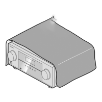
Crucial steps for safely discharging capacitors before disassembly.
Essential information for correct grounding during repair.
Specifies when adjustments are needed after part replacement.
Instructions for updating the unit's firmware.
Detailed procedure for updating the main microcomputer firmware.
Steps for updating the SUB microcomputer firmware.
Procedure for adjusting idle current for amplifier channels.
Schematic diagram for the audio assembly.
Schematic for AMP7 assembly, part 1.
Schematic for AMP7 assembly, part 2.
Schematic for AMP5 assembly, part 1.
Schematic for AMP5 assembly, part 2.
Schematic diagram for the main assembly.
D-MAIN assembly schematic, part 1.
D-MAIN assembly schematic, part 2.
D-MAIN assembly schematic, part 3.
D-MAIN assembly schematic, part 4.
D-MAIN assembly schematic, part 5.
D-MAIN assembly schematic, part 6.
D-MAIN assembly schematic, part 7.
D-MAIN assembly schematic for VSX-822-K, part 1.
| Channels | 5.1 |
|---|---|
| Amplifier Type | Class D |
| HDMI Inputs | 4 |
| HDMI Outputs | 1 |
| HDMI Version | 1.4a |
| 3D Support | Yes |
| Audio Return Channel (ARC) | Yes |
| Audio Formats Supported | Dolby TrueHD, DTS-HD Master Audio |
| Network Connectivity | Ethernet |
| AirPlay | Yes |
| Component Video Inputs | 1 |
| Composite Video Inputs | 2 |
| Digital Audio Inputs (Optical) | 2 |
| Digital Audio Inputs (Coaxial) | 1 |
| Phono Input | No |
| Multi-Channel Pre-Out | No |
| Bluetooth | No |
| Auto MCACC | Yes |
| Power Output (8 ohms, 20Hz-20kHz, 0.08% THD) | 80 W |
| Power Output (Watts per Channel) | 80W |
| USB Port | 1 |
| Standby Power Consumption | 0.1 Watts |
| Dimensions (W x H x D) | 435 x 148 x 321 mm |
| Weight | 8.5 kg |