Do you have a question about the Pioneer VSX-D912-S and is the answer not in the manual?
Check leakage current to earth ground for customer protection.
Notice on safety-related characteristics of replacement parts.
Conform to regulations and follow safety instructions during servicing.
Perform adjustments to maintain original product performance and specifications.
Clean parts properly to restore their performance, especially optical components.
Details of packing procedures and components.
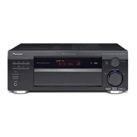
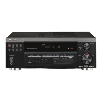
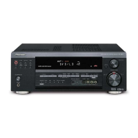
Exploded view of the exterior parts of the unit.
Exploded view of the front panel components.
Overall block diagram illustrating system functions and connections.
Schematic diagram for the Main Assembly (Part 1 of 3).
PCB connection diagram for the Main Assembly.
Adjustment procedures for the Tuner section.
Procedures for diagnosing the unit.
List of parts used in the unit.
Detailed explanations of various circuits and operations.
Instructions for cleaning internal and external parts of the unit.
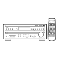
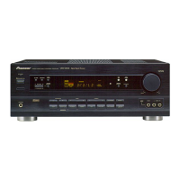
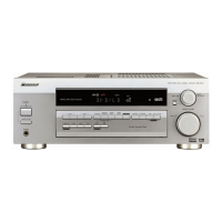
Overview of controls and indicators on the front panel.
Overview of input/output connectors on the rear panel.
| Response Bandwidth | 5 Hz - 100 kHz |
|---|---|
| Signal-To-Noise Ratio | 100 dB |
| Total Harmonic Distortion | 0.08% |
| Input Impedance | 47 kOhms |
| Input Sensitivity | 200 mV |
| Audio D/A Converter | 24-bit/192 kHz |
| Tuner Bands | AM/FM |
| Preset Station Qty | 30 |
| Power Output | 100 W per channel (8 ohms) |
| Audio Formats Supported | Dolby Digital, DTS |
| Amplifier Output Details | 100W per channel (8 ohms, 20Hz-20kHz, 0.08% THD) |
| Surround Sound Effects | Dolby Digital, DTS, Dolby Pro Logic II |
| Sound Effects | Virtual Surround |
| Tuning Range | FM: 87.5 - 108 MHz |
| Connectors | Composite video, Component video, Optical digital, Coaxial digital |
| Speaker Impedance | 8 ohms |
| Frequency Response | 20 Hz - 20 kHz |