Do you have a question about the Pioneer VSX-D938TX and is the answer not in the manual?
Alerts users about potential hazards, including lead content and California Proposition 65 compliance.
Highlights safety characteristics of electrical/mechanical parts and the importance of using recommended replacements.
Outlines essential safety checks, including leakage current measurement procedures.
Shows the high-level functional blocks and signal flow of the receiver.
Step-by-step guide for performing idle current adjustment on amplifier channels.
Step-by-step instructions for disassembling the unit and its major assemblies.
| Channels | 5.1 |
|---|---|
| Total Harmonic Distortion (THD) | 0.09% |
| Input Impedance | 47 kOhms |
| Signal-to-Noise Ratio | 100 dB |
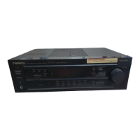
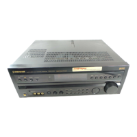
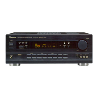
| Type | AV Receiver |
| Input Sensitivity | 200 mV |
| Output Signal to Noise Ratio | 100 dB |
| Digital Inputs | Coaxial, Optical |
| Surround Sound Formats | Dolby Digital, DTS |
| Frequency Response | 5 Hz - 100 kHz |
| Weight | 13.3 kg |
| Video Connections | Composite, S-Video |
| Impedance | 8 Ω |
| Power Output (per channel) | 100W (8 ohms, 20Hz-20kHz, 0.09% THD) |