EasyManua.ls Logo

Pioneer VSX-D457 User Manual

Pioneer VSX-D457
10 pages
To Next Page IconTo Next Page
Page #1 background imageLoading...
Page #1 background image
ORDER NO.
PIONEER ELECTRONIC CORPORATION 4-1, Meguro 1-Chome, Meguro-ku, Tokyo 153-8654, Japan
PIONEER ELECTRONICS SERVICE, INC. P.O. Box 1760, Long Beach, CA 90801-1760, U.S.A.
PIONEER ELECTRONIC (EUROPE) N.V . Haven 1087, Keetberglaan 1, 9120 Melsele, Belgium
PIONEER ELECTRONICS ASIACENTRE PTE. LTD. 501 Orchard Road, #10-00 Wheelock Place, Singapore 238880
PIONEER ELECTRONIC CORPORATION 1998
AUDIO/VIDEO MULTI-CHANNEL RECEIVER
RRV1965
VSX-D507S
VSX-D457
1. CONTRAST OF MISCELLANEOUS PARTS ..... 2
2. SCHEMATIC DIAGRAM.....................................6
CONTENTS
T–ZZR MAY 1998 Printed in Japan
Refer to the service manual RRV1911 for VSX-D507S/KUXJI.
THIS MANUAL IS APPLICABLE TO THE FOLLOWING MODEL(S) AND TYPE(S).
Model
VSX-D507S VSX-D457
Type Power Requirement
The voltage can be converted by
the following method.
‡‡AC110V/120–127V/220V/240V With the voltage selector
AC110V/120–127V/220V/240V With the voltage selector
SDXJI
SDXJI/NC
www.freeservicemanuals.info
12/9/2016
Published in Heiloo, Holland
Question and Answer IconNeed help?

Do you have a question about the Pioneer VSX-D457 and is the answer not in the manual?

Pioneer VSX-D457 Specifications

General IconGeneral
BrandPioneer
ModelVSX-D457
CategoryReceiver
LanguageEnglish

Summary

Service Manual Overview

Applicable Models and Types

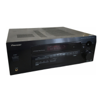
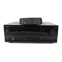
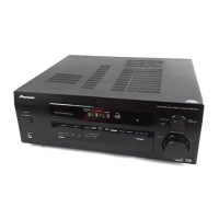
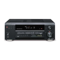
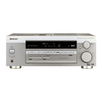
Details the specific Pioneer receiver models (VSX-D507S, VSX-D457) and types covered by this service manual.

Contrast of Miscellaneous Parts

Part Notes and Safety Markings

Explains part availability (NSP) and the significance of safety factor markings on components.

Resistor Code Conversion Examples

Provides examples for converting resistance values into code form for ordering parts.

Model-Specific Part Differences

Compares part numbers for VSX-D507S/SDXJI, SDXJI/NC and VSX-D457/SDXJI models.

Exploded Views - Exterior Section

Exterior Section Diagram

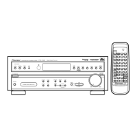
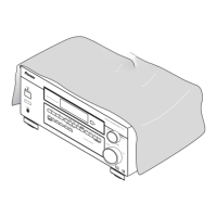
Illustrates the external components and their arrangement for the receiver unit.

Contrast of PCB Assemblies

Input Assy Comparison

Details differences in the Input Assy part numbers between receiver models.

HP & FAV Assy Comparison

Highlights variations in the HP & FAV Assy part numbers across models.

FL & UCOM Assy Comparison

Lists part number discrepancies for the FL & UCOM Assy across different models.

Power Supply Assy Comparison

Compares the part numbers for the Power Supply Assy for various models.

Video Assy Part Contrast

Video Assy Part Differences

Compares part numbers for the Video Assy between different receiver models.

Schematic Diagrams - FL & UCOM Assy

FL & UCOM Assy Circuit Diagram (Part 1)

Presents the schematic diagram for the FL & UCOM Assembly, including connector CN101.

FL & UCOM Assy Circuit Diagram (Part 2)

Continuation of the FL & UCOM Assembly schematic, detailing front block and component functions.

Schematic Diagrams - Power Supply Assy

Power Supply Assy Schematic (AWX7096)

Circuit diagram for the Power Supply Assy (AWX7096), showing impedance selector.

Power Supply Assy Schematic (AWX7101)

Detailed schematic for the Power Supply Assy (AWX7101), including transformer and voltage selector.

Schematic Diagrams - Video Assy

Video Assy Circuit Diagram

Presents the schematic diagram for the Video & SR Block Assy.

Related product manuals