EasyManua.ls Logo

Pioneer VSX-D407 User Manual

Pioneer VSX-D407
61 pages
To Next Page IconTo Next Page
Page #1 background imageLoading...
Page #1 background image
ORDER NO.
PIONEER CORPORATION 4-1, Meguro 1-chome, Meguro-ku, Tokyo 153-8654, Japan
PIONEER ELECTRONICS SERVICE, INC. P.O. Box 1760, Long Beach, CA 90801-1760, U.S.A.
PIONEER EUROPE N.V. Haven 1087, Keetberglaan 1, 9120 Melsele, Belgium
PIONEER ELECTRONICS ASIACENTRE PTE. LTD. 253 Alexandra Road, #04-01, Singapore 159936
PIONEER CORPORATION 2000
c
RRV2252
1. SAFETY INFORMATION
......................................
2
2. EXPLODED VIEWS AND PARTS LIST
...............
3
3. BLOCK DIAGRAM AND SCHEMATIC DIAGRAM
.....
8
4. PCB CONNECTION DIAGRAM
.........................
26
5. PCB PARTS LIST
...............................................
39
6. ADJUSTMENT
....................................................
47
CONTENTS
7. GENERAL INFORMATION
................................
48
7.1 DISASSEMBLY
............................................
48
7.2 PARTS
..........................................................
49
7.2.1 IC
............................................................
49
7.2.2 DISPLAY
.................................................
54
8. PANEL FACILITIES AND SPECIFICATIONS
.......
56
T – ZZK JAN. 2000 Printed in Japan
Type
Model
Power Requirement Remarks
VSX-D409 VSX-D309
KUXJI AC120V
KCXJI AC120V
THIS MANUAL IS APPLICABLE TO THE FOLLOWING MODEL(S) AND TYPE(S).
PHONES
MPX
MODE
@ @
MIDNIGHT
2
/DTS
SIGNAL
SELECT
1
R
N∫m-Û≤?/ Digital Signal Processor
AUDIO/VIDEO MULTI-CHANNEL RECEIVER
VSX-D409
VSX-D309
Question and Answer IconNeed help?

Do you have a question about the Pioneer VSX-D407 and is the answer not in the manual?

Pioneer VSX-D407 Specifications

General IconGeneral
BrandPioneer
ModelVSX-D407
CategoryReceiver
LanguageEnglish

Summary

Safety Information

Safety Precautions

Guidelines for technician and customer safety, focusing on leakage current.

Product Safety Notice

Identifies safety-related components and hazards, emphasizing genuine replacement parts.

Exploded Views and Parts List

Packing Information

Lists packing materials and accessories included with the product.

Exterior Section Overview

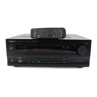
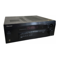
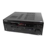
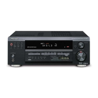
Details the exterior layout and lists associated parts for identification.

Front Panel Section Details

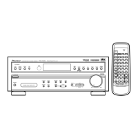
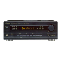
Details the front panel components and provides their respective parts list.

Block Diagram and Schematic Diagrams

Block Diagram Overview

Visual representation of signal flow and component interconnections within the receiver.

D.D & Input Assy Schematics

Schematic diagrams detailing the D.D & Input Assy across multiple pages.

Amplifier and Transistor Assembly Schematics

Schematic diagrams for Amplifier, Trans2, Trans3, Regulator, and Trans1 assemblies.

Video, H.P., Digital In, and Front Panel Schematics

Schematic diagrams for Video&6CH, H.P., Digital In, and Front panel assemblies.

PCB Connection Diagrams

Digital In Assy PCB Connection

PCB connection diagram for the Digital In Assy, showing component layout.

Transistor, Regulator, and Input Assy PCB Connections

PCB connection diagrams for Regulator, Trans3, Trans1, and Trans2 assemblies.

Amp Input, Amp&Primary PCB Connections

PCB connection diagrams for Amp Input and Amp&Primary assemblies.

D.D & Input Assy PCB Connection

PCB connection diagram for the D.D & Input Assy.

Front, H.P., R.Encoder, Power SW PCB Connections

PCB diagrams for Front, H.P. Assy, and Power SW Assy.

Video&6CH In Assy PCB Connection

PCB diagram for the Video&6CH In Assy.

PCB Parts List

PCB Assembly Contrast and Specific Part Differences

Compares parts across PCB assemblies and lists specific model differences.

General VSX-D409 PCB Component Lists

Lists semiconductors, connectors, coils, filters, capacitors, and resistors for VSX-D409.

Assembly Specific PCB Parts Lists

Lists parts for various assemblies like Amp&Primary, Trans2, Regulator, etc.

Adjustment Procedures

General Information and Parts

Disassembly Instructions

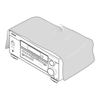
Provides step-by-step instructions and diagrams for disassembling the unit.

Parts Identification

Lists available parts for the unit and their locations.

PCB Location Diagram

Diagram showing the physical location of various PCB assemblies within the unit.

Integrated Circuit (IC) Details

Lists integrated circuits (ICs) used in the unit with their pin functions.

Display Unit Information

Details block diagrams and pin functions for display-related ICs.

Panel Facilities and Specifications

Front Panel Controls and Indicators

Describes the functions of the buttons and indicators on the front panel.

Display Indicators and Functions

Explains the meaning of various display indicators and their functions.

Remote Control Operation

Mode Selection and DSP Functions

Explains multi-control, RECEIVER, NUMBER/MODE, DSP, MIDNIGHT, 5.1 CH buttons.

Tuner, Volume, and Signal Setup Controls

Details tuner controls, LOUDNESS, VOLUME, SIGNAL SELECT, and other setup buttons.

DVD Player, TV Controls, and Other Functions

Covers DVD player menus, TV controls, EFFECT, and MENU buttons.

Connecting Audio Components

Audio/Video Cords and Connections

Guidance on using audio/video cords and making connections.

Cassette Deck Placement Advice

Advice on positioning cassette decks to avoid noise interference.

Technical Specifications

Amplifier Section Specifications

Lists power output, distortion, and frequency response for the amplifier.

Video and Tuner Sections Specifications

Technical specs for video, FM, and AM tuner sections.

Miscellaneous Specifications

Lists power requirements, dimensions, weight, and furnished parts.

Included Accessories

Lists included accessories like antennas, batteries, and remote control.

Related product manuals