EasyManua.ls Logo

Pioneer VSX-D710S Service Manual

Pioneer VSX-D710S
60 pages
To Next Page IconTo Next Page
Page #1 background imageLoading...
Page #1 background image
ORDER NO.
PIONEER CORPORATION 4-1, Meguro 1-chome, Meguro-ku, Tokyo 153-8654, Japan
PIONEER ELECTRONICS SERVICE, INC. P.O. Box 1760, Long Beach, CA 90801-1760, U.S.A.
PIONEER EUROPE NV Haven 1087, Keetberglaan 1, 9120 Melsele, Belgium
PIONEER ELECTRONICS ASIACENTRE PTE. LTD. 253 Alexandra Road, #04-01, Singapore 159936
PIONEER CORPORATION 2001
c
RRV2432
1. SAFETY INFORMATION
......................................
2
2. EXPLODED VIEWS AND PARTS LIST
...............
3
3. BLOCK DIAGRAM AND SCHEMATIC DIAGRAM
.....
8
4. PCB CONNECTION DIAGRAM
.........................
28
5. PCB PARTS LIST
...............................................
43
6. ADJUSTMENT
....................................................
47
CONTENTS
7. GENERAL INFORMATION
................................
48
7.1 DISASSEMBLY AND DIAGNOSIS
...............
48
7.2 PARTS
..........................................................
50
7.2.1 IC
............................................................
50
7.2.2 DISPLAY
.................................................
53
8. PANEL FACILITIES AND SPECIFICATIONS
.......
55
T – ZZK MAR. 2001 Printed in Japan
THIS MANUAL IS APPLICABLE TO THE FOLLOWING MODEL(S) AND TYPE(S).
AUDIO/VIDEO MULTI-CHANNEL RECEIVER
VSX-D710S
Type
Model
Power Requirement Remarks
VSX-D710S
MYXJIEW AC220-230V
MYXJIGR AC220-230V
MVXJI AC230V
1
N∫m-Û≥,?∫

Other manuals for Pioneer VSX-D710S

Question and Answer IconNeed help?

Do you have a question about the Pioneer VSX-D710S and is the answer not in the manual?

Pioneer VSX-D710S Specifications

General IconGeneral
BrandPioneer
ModelVSX-D710S
CategoryReceiver
LanguageEnglish

Summary

1. SAFETY INFORMATION

Safety Precautions and Notices

Covers essential safety information, precautions, and warnings for safe operation and repair.

3. BLOCK DIAGRAM AND SCHEMATIC DIAGRAM

3.1 Block Diagram

Visual representation of the receiver's signal paths and functional blocks.

3.2 OVERALL WIRING CONNECTION DIAGRAM

Overall Wiring Diagram

Illustrates the interconnections between all major internal assemblies.

3.3 D.D & INPUT ASSY (1/3)

D.D & Input Assembly Schematic (1/3)

Detailed schematic for the D.D & Input Assembly, part 1 of 3.

3.3 D.D & INPUT ASSY (2/3)

3.4 D.D & INPUT ASSY (2/3)

D.D & Input Assembly Schematic (2/3)

Detailed schematic for the D.D & Input Assembly, part 2 of 3.

3.5 D.D & INPUT ASSY (3/3)

D.D & Input Assembly Schematic (3/3)

Detailed schematic for the D.D & Input Assembly, part 3 of 3.

3.6 AMP&PRIMARY (1/2), TRANS2 and TRANS3 ASSYS

3.6 AMP&PRIMARY (2/2), TRANS2 and TRANS3 ASSYS

3.7 AMP&PRIMARY (2/2), REGULATOR, AMP INPUT, TRANS1, MECHA SW and TRANS4 ASSYS

3.8 VIDEO&6CH IN, H. P. and DIGITAL IN ASSYS

3.9 DIGITAL IN ASSY

3.9 FRONT, R. ENCODER and POWER SW ASSYS

3.10 S. VIDEO, BOARD TO BOARD, FRONT VIDEO and COMPONENT ASSYS

6. ADJUSTMENT

Adjustment Procedures

Provides information and procedures for adjusting the unit.

7. GENERAL INFORMATION

7.1 Disassembly and Diagnosis

Procedure for disassembling the unit and diagnosing common issues.

7.1 Diagnosis of D.D & INPUT Assy

D.D & Input Assy Diagnosis

Specific diagnostic steps for the D.D & Input Assembly.

7.2 PARTS

7.2.1 IC (Integrated Circuits)

Lists Integrated Circuits (ICs) with pin functions and assignments for PDG260A.

7.2.1 IC

7.2.2 DISPLAY

FL Display and Grid Assignment

Information on the FL Display, including pin assignment and segment grid layout.

8. PANEL FACILITIES AND SPECIFICATIONS

Front Panel Controls and Indicators

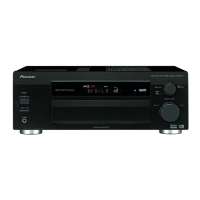
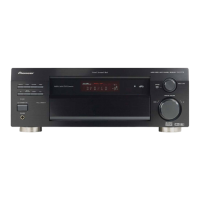
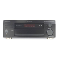
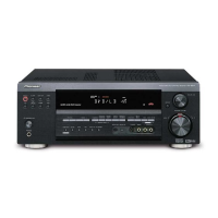
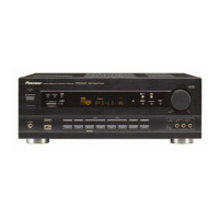
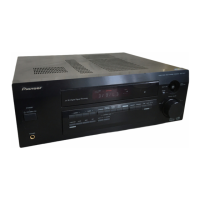
Details the function and operation of front panel controls like power, signal selection, DSP, volume, and input jacks.

8.1 PANEL FACILITIES

Remote Control

Remote Control Buttons (1-8)

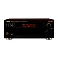
Describes the function of SOURCE, MULTI CONTROL, RCV, NUMBER/MODE, MIDNIGHT, 5.1/7.1, ATT buttons.

Remote Control

8.2 SPECIFICATIONS

Amplifier Section Specifications

Technical specifications for the amplifier section, including power output and input sensitivity.

Related product manuals