EasyManua.ls Logo

Pioneer VSX-D712-K User Manual

Pioneer VSX-D712-K
91 pages
To Next Page IconTo Next Page
Page #1 background imageLoading...
Page #1 background image
ORDER NO.
PIONEER CORPORATION 4-1, Meguro 1-chome, Meguro-ku, Tokyo 153-8654, Japan
PIONEER ELECTRONICS (USA) INC. P.O. Box 1760, Long Beach, CA 90801-1760, U.S.A.
PIONEER EUROPE NV Haven 1087, Keetberglaan 1, 9120 Melsele, Belgium
PIONEER ELECTRONICS ASIACENTRE PTE. LTD. 253 Alexandra Road, #04-01, Singapore 159936
PIONEER CORPORATION 2003
DOWN UP
ENTER
MASTER VOLUME
MULTI JOG
PHONES
STANDBY
STANDBY/ON
PULL OPEN
DVD/LD TV/SAT VCR/DVR VIDEO
CD
CD-R/
TAPE/MD
TUNER
AUX
VSX-D712-K
RRV2754
AUDIO/VIDEO MULTI-CHANNEL RECEIVER
VSX-D712-K
THIS MANUAL IS APPLICABLE TO THE FOLLOWING MODEL(S) AND TYPE(S).
Model Type Power Requirement Remarks
VSX-D712-K KUXJI AC120V
VSX-D712-K KCXJI AC120V
For details, refer to "Important symbols for good services".
T-ZZK FEB. 2003 printed in Japan
Question and Answer IconNeed help?

Do you have a question about the Pioneer VSX-D712-K and is the answer not in the manual?

Pioneer VSX-D712-K Specifications

General IconGeneral
TypeAV Receiver
Channels5.1
Input Sensitivity200 mV
Analog Inputs5
Speaker TerminalsBinding posts
Tuner TypeAM/FM
Power Output100 W per channel (8 ohms)
Frequency Response5 Hz - 100 kHz
Speaker Load Impedance6 ohms
Digital Inputs2 optical, 1 coaxial
Video Inputs3 x composite, 1 x component
Video Outputs1 x composite, 1 x component
Dimensions (W x H x D)420 x 151 x 370 mm
Weight9.5 kg
Outputs5.1 channel

Summary

Safety Information and Precautions

Warning on Hazardous Materials

Contains lead and certain electrical parts chemicals known to cause cancer or reproductive harm.

Safety Precautions: Leakage Current Check

Check leakage current to ensure no shock hazard. Must not exceed 0.5 mA.

Product Safety Notice

Identifies special safety-related component characteristics essential for product safety.

Product Specifications

Diagrams and Schematics

Main Assembly Schematic (1/3)

Provides the schematic diagram for the main assembly, part 1 of 3.

Adjustment Procedures

Tuner Section Adjustment

Details the adjustment procedure for the FM tuner section.

General Information and Diagnosis

Detection Circuits

Diagrams for DC detection, overload, and fan stop protection circuits.

Amplifier System Protection Operation

Details system protection behavior for various abnormalities.
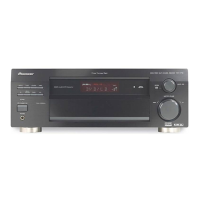
Related product manuals