EasyManua.ls Logo

Pioneer VSX-D307 Service Manual

Pioneer VSX-D307
48 pages
To Next Page IconTo Next Page
Page #1 background imageLoading...
Page #1 background image
@)
PIONEER’
The
Art
of
Entertainment
Service
Manual
AUDIO/VIDEO
MULTI-CHANNEL
RECEIVER
VSX-D307
THIS
eal
dananes
IS
APPLICABLE
TO
THE
FOLLOWING
MODEL(S)
AND
TYPE(S).
KUXJ
oa
AC120V
ORDER
NO.
RRV1925
KUXJI
ow
AC120V
Kox___|__©__|acia0v
[[_>
"~~
CONTENTS
1.
SAFETY
INFORMATION
.....0..
eee
eens
2
7.
GENERAL
INFORMATION
2.
EXPLODED
VIEWS
AND
PARTS
LIST...........00
3
VA
APART
Ss
etesdadien.ddscsscadtitieer
sittin
the
vats
3.
SCHEMATIC
DIAGRAM
............cecccseeeeeeeeeseeseseeee
8
Pill
WGi
ks
Boe
ee
Ses
Aah
tececiecsesiecscusrienstns
4.
PCB
CONNECTION
DIAGRAM
..........::ccceeeeeeee
24
£.4.2>
DISPLAY
sisscccivteatvcea
rc
dnnceiecnieaavents
5.
PCB
PARTS
LIST
...
be
7.2
DISASSEMBLY
....
6.
ADJUSTMENT
.........
ces
ccceeeeseseeseceeeeeerseseneereneeneee
7:3:
DIAGNOSIS
S.
siscsivenctsataaeanvavehy,
7.4
BLOCK
DIAGRAM
..........ccccesseeeteeesereeteees
42
8.
PANEL
FACILITIES
AND
SPECIFICATIONS...
44
PIONEER
ELECTRONIC
CORPORATION
4-1,
Meguro
1-Chome,
Meguro-ku,
Tokyo
153-8654,
Japan
PIONEER
ELECTRONICS
SERVICE,
INC.
P.O.
Box
1760,
Long
Beach,
CA
90801-1760,
U.S.A.
PIONEER
ELECTRONIC
(EUROPE)
N.V.
Haven
1087,
Keetberglaan
1,
9120
Melsele,
Belgium
PIONEER
ELECTRONICS
ASIACENTRE
PTE. LTD.
501
Orchard
Road,
#10-00
Lane
Crawford
Place,
Singapore
0923
©
PIONEER
ELECTRONIC
CORPORATION
1998
;
,
;
T-IZM
MAR.
1998
Printed
in
Belgium

Other manuals for Pioneer VSX-D307

Question and Answer IconNeed help?

Do you have a question about the Pioneer VSX-D307 and is the answer not in the manual?

Pioneer VSX-D307 Specifications

General IconGeneral
BrandPioneer
ModelVSX-D307
CategoryReceiver
LanguageEnglish

Summary

SAFETY INFORMATION

SAFETY PRECAUTIONS AND NOTICES

Essential safety checks, warnings, and product safety notices.

EXPLODED VIEWS AND PARTS LIST

PACKING AND ACCESSORIES

Lists packing materials and accessories.

EXTERIOR AND FRONT PANEL PARTS

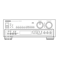
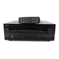
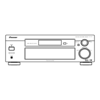
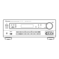
Details external and front panel components.

MODEL VARIATION TABLE

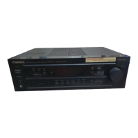
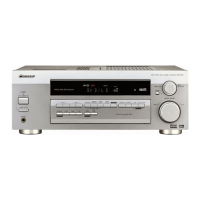
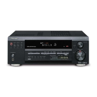
Shows differences between specific model variants.

SCHEMATIC DIAGRAMS

OVERALL CONNECTION DIAGRAM

Shows the main connection flow between unit assemblies.

MAJOR ASSEMBLY SCHEMATICS

Detailed schematics for key assemblies like Mother, Front, and DSP.

PCB CONNECTION AND PARTS LISTS

PCB CONNECTION DIAGRAMS

Diagrams showing PCB component layouts and connections.

PCB PARTS LISTS

Lists of components for various PCB assemblies.

GENERAL INFORMATION

PARTS, IC, DISPLAY INFO

Details on parts, ICs, and display elements.

DISASSEMBLY AND DIAGNOSIS

Procedures for disassembling and diagnosing the unit.

BLOCK DIAGRAM AND TEST POINTS

System block diagram and test point locations.

PANEL FACILITIES AND SPECIFICATIONS

FRONT PANEL CONTROLS

Description of front panel buttons and indicators.

UNIT SPECIFICATIONS

Technical specifications for amplifier, tuners, and video sections.

CONNECTING DEVICES AND REMOTE CONTROL

CONNECTION GUIDELINES AND TERMINALS

Setup advice for antennas, and descriptions of connectors.

REMOTE CONTROL OPERATION

Explains functions of the remote control unit buttons.

Related product manuals