EasyManua.ls Logo

Pioneer VSX-D811S Service Manual

Pioneer VSX-D811S
90 pages
To Next Page IconTo Next Page
Page #1 background imageLoading...
Page #1 background image
ORDER NO.
PIONEER CORPORATION 4-1, Meguro 1-chome, Meguro-ku, Tokyo 153-8654, Japan
PIONEER ELECTRONICS (USA) INC. P.O. Box 1760, Long Beach, CA 90801-1760, U.S.A.
PIONEER EUROPE NV Haven 1087, Keetberglaan 1, 9120 Melsele, Belgium
PIONEER ELECTRONICS ASIACENTRE PTE. LTD. 253 Alexandra Road, #04-01, Singapore 159936
PIONEER CORPORATION 2002
RRV2614
THIS MANUAL IS APPLICABLE TO THE FOLLOWING MODEL(S) AND TYPE(S).
T – ZZK MAY. 2002 Printed in Japan
Model No. Order No. Remarks
VSX-D811S/KUXJI RRV2583
This service manual should be used together with the following manual(s):
AUDIO/VIDEO MULTI-CHANNEL RECEIVER
VSX-41
Type
Model
Power Requirement Remarks
VSX-41
KUXJI/CA AC120V
w
w
w
.
x
i
a
o
y
u
1
6
3
.
c
o
m
Q
Q
3
7
6
3
1
5
1
5
0
9
9
2
8
9
4
2
9
8
T
E
L
1
3
9
4
2
2
9
6
5
1
3
9
9
2
8
9
4
2
9
8
0
5
1
5
1
3
6
7
3
Q
Q
TEL 13942296513 QQ 376315150 892498299
http://www.xiaoyu163.com
Question and Answer IconNeed help?

Do you have a question about the Pioneer VSX-D811S and is the answer not in the manual?

Pioneer VSX-D811S Specifications

General IconGeneral
Channels5.1
Surround Sound FormatsDolby Digital, DTS
TunerAM/FM
Preset Stations30
Remote ControlYes
Input Sensitivity200 mV
Speaker load impedance6-16 ohms
Power Output100 watts per channel (8 ohms)
Frequency Response5Hz to 100kHz
Digital Inputs2 optical, 1 coaxial
Analog Inputs5 x RCA
Video Connections3 x Composite, 2 x S-Video, 1 x Component
OutputsSpeakers, Subwoofer, Headphones
Dimensions (W x H x D)17.1 x 6.6 x 15.4 inches
Signal-to-Noise Ratio100 dB

Summary

Contrast of Miscellaneous Parts

Contrast Table: VSX-D811S vs. VSX-41

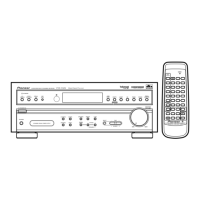
Details part differences between VSX-D811S/KUXJI and VSX-41/KUXJI/CA models.

Schematic Diagram: Digital In Assembly

Schematic Diagram: Front Assy

Product Specifications Overview

Amplifier Section Specifications

Lists specifications for power output, frequency response, and input sensitivity.

FM Tuner Section Specifications

Lists specifications for frequency range, sensitivity, and stereo separation.

AM Tuner Section Specifications

Lists specifications for frequency range, sensitivity, and signal-to-noise ratio.

Video Section Specifications

Lists specifications for video input, output, frequency response, and signal-to-noise ratio.

Miscellaneous Specifications Details

Covers power requirements, consumption, dimensions, and furnished parts.

Important Service Symbols and Guidelines

Product Safety and Servicing Guidelines

Emphasizes adherence to regulations and safety during servicing.

Exterior Section Parts List and Model Contrast

Exterior Section Parts List Details

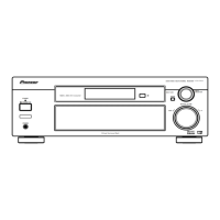
Lists parts for the exterior section with their part numbers and descriptions.

Exterior Parts Contrast Table

Details part number differences for exterior components across different models.

Front Panel Parts List and Model Contrast

Front Panel Section Parts List Details

Lists parts for the front panel section with their part numbers and descriptions.

System Block Diagrams Overview

Block Diagrams: Audio and Control Sections

Overall Wiring Connection Diagram

Wiring Connections for Power, H.P., and Trans Assemblies

Schematic Diagram: DD & Input Assy (1/4)

Schematic Diagram: DD & Input Assy (2/4)

Schematic Diagram: DD & Input Assy (3/4)

Schematic Diagram: DD & Input Assy (4/4)

Schematic Diagrams: Amp, Trans2, Trans3 Assemblies

Schematic Diagrams: Amp (2/2), Reg, Hashigeta, B to B, Trans1

Schematic Diagrams: Digital In and Kawa Assemblies

Schematic Diagrams: Video, 6CH In, S. Video Assemblies

Schematic Diagrams: Front, R. Encoder, Power SW, H.P. Assemblies

Schematic Diagrams: Trans4, F. Video, F. Optical, H.P., M. SW, Pri-Out

Schematic Diagram: FM/AM Tuner Module

PCB Connection Diagrams: Trans Assemblies

PCB Connection Diagram: DD & Input Assy

PCB Connection Diagram: DD & Input Assy (Side B)

PCB Connection Diagrams: Amp & Mecha SW Assemblies

PCB Connection Diagrams: Front, R. Encoder, Power SW, H.P. Assemblies

PCB Connection Diagrams: Regulator, Hashigeta, Kawa Assemblies

PCB Connection Diagrams: Board-to-Board, Digital In, Video, 6CH In Assemblies

PCB Connection Diagrams: S. Video, Front Video, Front Optical, Pri-Out Assemblies

PCB Connection Diagram: FM/AM Tuner Module

Tuner Section Adjustment Procedures

FM Tuner Section Adjustment Steps

Provides steps for adjusting the FM tuner section using specific input levels and conditions.

IC Pin Functions: Part 1

IC Pin Functions: Part 2

Key IC Details: AK4586VQ, NJU7312AM, PD8097A, AK4382AVT

AK4586VQ IC Pin Arrangement and Block Diagram

Shows pin arrangement and block diagram for the AK4586VQ CODEC IC.

NJU7312AM IC Pin Arrangement and Block Diagram

Shows pin arrangement and block diagram for the NJU7312AM Analog Switch Array IC.

PD8097A IC Pin Arrangement and Block Diagram

Shows pin arrangement and block diagram for the PD8097A 4Mb P2ROM IC.

AK4382AVT IC Pin Arrangement and Block Diagram

Shows pin arrangement and block diagram for the AK4382AVT D/A Converter IC.

AK4586VQ IC Pin Functions (Part 1)

AK4586VQ IC Pin Functions (Part 2)

IC Pin Functions: BD3812F and NJU7312AM

BD3812F IC Pin Functions

Lists pin names, I/O, and functions for the BD3812F IC.

NJU7312AM IC Pin Functions

Lists pin names, I/O, and functions for the NJU7312AM IC.

PD8097A IC Pin Functions

AK4382AVT IC Pin Functions

U-COM System Block Diagram

Power On Sequence Timing Diagram

Power Off Sequence Timing Diagram

Protection Circuit Operation Details

DC Abnormal Detection Mechanism

Describes the process when DC abnormal detection is triggered, including A.MUTE and power supply actions.

Overload Detection Mechanism

Explains the process when overload detection is triggered, including A.MUTE and power supply actions.

Remote Control Button Functions (Part 1)

Remote Control Button Functions (Part 1)

Explains SOURCE, MULTI CONTROL, RCV, Number buttons, DISC, TEST TONE, and Receiver Control buttons.

Remote Control Button Functions (Part 2)

Remote Control Button Functions (Part 2)

Explains T.EDIT, BAND, CLASS, DISPLAY, RF ATT, DVD controls, TOP MENU, AUDIO, SUBTITLE, ANGLE, REMOTE SETUP, RECEIVER controls, and MENU buttons.

Related product manuals