Do you have a question about the Pioneer VSX-D810S and is the answer not in the manual?
Essential safety precautions and warnings for service technicians.
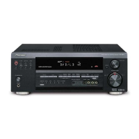
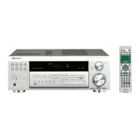
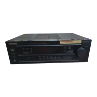
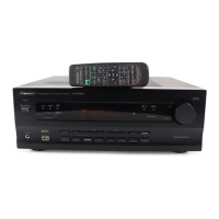
Detailed visual breakdown of the unit and its components.
Illustrates the functional blocks and circuit schematics of the receiver.
Procedures for calibrating and adjusting the unit's performance.
Alerts users about hazardous materials in the product.
Guidelines for safe operation and maintenance.
Highlights safety-related characteristics of components.
Illustrates the overall functional blocks of the receiver's circuitry.
Shows interconnections between different assemblies and PCBs.
Schematic diagram for the D.D UCOM assembly (Part 1/2).
Schematic diagram for the D.D DSP assembly (Part 1/4).
Schematic diagram for Amplifier & Primary assemblies.
Schematic for Regulator and Amplifier Input assemblies.
Step-by-step guide for disassembling the unit and basic diagnosis.
Technical specifications for the amplifier and tuner sections.