Do you have a question about the Pioneer VSX-D411 and is the answer not in the manual?
Details the continuous average power output and frequency response of the amplifier section.
Presents the overall block diagram of the receiver's main functional units.
Illustrates the interconnections between various sub-assemblies and boards.
Provides the schematic diagram for the D.D & Input (1/4) assembly.
Provides the schematic diagram for the D.D & Input (2/4) assembly.
Provides the schematic diagram for the D.D & Input (3/4) assembly.
Provides the schematic diagram for the D.D & Input (4/4) assembly.
Schematics for amplifier and primary sections, plus Trans2 and Trans3 assemblies.
Schematics for amplifier, regulator, amp input, and Trans1 assemblies.
Schematics for video, 6-channel input, and S-video assemblies.
Schematics for front panel, R.Encoder, and power switch assemblies.
Schematics for digital input, headphone jack, and Kawa assemblies.
| Channels | 5.1 |
|---|---|
| Power Output (per channel) | 100 W |
| Total Harmonic Distortion (THD) | 0.09 % |
| Frequency Response | 5 Hz - 100 kHz |
| Input Sensitivity | 200 mV |
| Signal-to-Noise Ratio | 100 dB |
| Type | AV Receiver |
| Input Impedance | 47 kΩ |
| Audio D/A Converter | 24-bit / 96 kHz |
| DSP | Yes |
| DSP Modes | 5 |
| Surround Sound Effects | Dolby Digital, DTS |
| Input Digital Coaxial | 1 |
| Input Digital Optical | 2 |
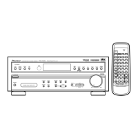
| Remote Control | Yes |
| Tuner Bands | AM/FM |
| Preset Station Qty | 30 |
| Output Power | 100W per channel |
| Speaker Impedance | 16 ohms |