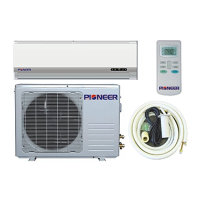
Do you have a question about the Pioneer WYT Series and is the answer not in the manual?
Provides information required for ordering spare parts efficiently and correctly.
Details the dimensions and specifications for the indoor unit of the air conditioner.
Details the dimensions and specifications for the outdoor unit of the air conditioner.
Illustrates the refrigeration cycle for both cooling-only and heat pump operation modes.
Explains the functions of each button on the remote controller for operating the unit.
Details how to set the remote controller type (Cooling Only vs. Heat Pump).
Outlines various safety protection mechanisms built into the electronic controller.
Describes the operation and settings of the 'Feel' mode for user comfort.
Explains how the compressor frequency is controlled in cooling mode.
Details the system operation and set temperature adjustments in DRY mode.
Describes frequency control and indoor fan motor control in HEATING mode.
Covers auto fan control, 4-way valve, and defrosting logic in heating mode.
Explains SLEEP mode, emergency operation, and auto-restart function.
Explains how error codes and protection statuses are displayed on the unit.
Lists various failure types and their corresponding LED and Digital LED codes.
Lists protection types and their corresponding function indicators and digital LED codes.
Explains the LED indicators on the outdoor power board for failure display.
Maps blink times to specific failure codes displayed on the outdoor power source board.
Provides the wiring diagram for specific indoor and outdoor unit models.
Shows the wiring diagram for the WYT012GLFI19RL model, including indoor and outdoor units.
Displays the wiring diagram for multiple WYT models, covering indoor and outdoor units.
Provides essential safety guidelines and recommendations for the installation process.
Outlines crucial safety rules and recommendations for the end-user during operation and maintenance.
Lists specific safety rules and prohibitions to prevent hazards and damage.
Identifies and lists the various parts of the indoor and outdoor units with corresponding numbers.
Details pipe sizes, lengths, and additional refrigerant requirements for installation.
Provides specifications for selecting appropriate wire sizes for connecting cables.
Provides guidelines for the initial installation of the indoor and outdoor units.
Details steps for mounting plate installation and drilling a piping hole in the wall.
Guides on making electrical connections for the indoor unit.
Details refrigerant piping connection, pipe joining, and water drainage.
Emphasizes proper condensed water drainage for successful installation.
Guides on making electronic connections for the outdoor unit.
Details pipe connection to outdoor unit and bleeding refrigerant circuit.
Illustrates the control diagram of the outdoor system, detailing its components and functions.
Shows the physical layout and components of the Outdoor Unit Printed Circuit Board (ODU PCB).
Provides a detailed connection diagram for the Outdoor Unit Printed Circuit Board (ODU PCB).
Illustrates the flow of electrical current between units and compressor.
Guides on troubleshooting and repairing issues related to E1 or E2 error displays.
Provides troubleshooting steps for errors indicated by E6 on the display.
Offers solutions for troubleshooting and repairing E3 or E7 error codes.
Details troubleshooting methods for errors indicated by E8 on the unit display.
Explains how to diagnose and fix communication faults indicated by E0 or E5 errors.
Provides troubleshooting guidance for current sensor faults indicated by EA.
Guides on troubleshooting drive circuit damage indicated by E9, P0, or P9.
Offers troubleshooting for voltage sensor damage indicated by EU error.
Provides solutions for EEPROM faults indicated by EE error display.
Explains how to address filter replacement alerts indicated by CL display.
A flowchart to diagnose malfunctions related to the outdoor unit's IPM or compressor.
Detailed procedure for diagnosing and resolving DC over current errors in the unit.
Flowchart to diagnose and resolve E0 and E5 errors, focusing on communication issues.
Lists temperature vs. resistance and voltage data for indoor and outdoor sensors.
Provides temperature vs. resistance data for outdoor unit sensors.
| Brand | Pioneer |
|---|---|
| Model | WYT Series |
| Category | Air Conditioner |
| Language | English |


 Loading...