Do you have a question about the Pioneer X-HM81-K and is the answer not in the manual?
Details on using lead-free solder and appropriate soldering irons for environmental protection.
Instructions on removing soldering on a short circuit point after connecting the pickup flexible cable.
Guidance on replacing the MAC address seal after replacing the CR870 module or BCO Assy.
Details power output, impedance, and headphone specifications for the audio amplifier.
Includes power source, consumption, dimensions, and weight information for the unit.
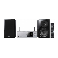
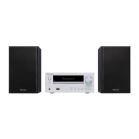
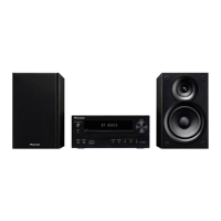
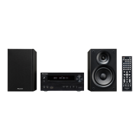
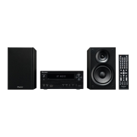
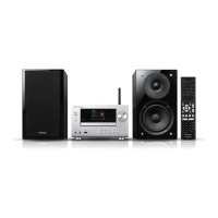
Lists all items included in the product package for different models.
Recommended checks to ensure product quality after service, covering audio and operations.
Lists essential jigs and their part numbers required for diagnosis and service operations.
Diagrams illustrating the physical placement of various PC boards within the unit.
Detailed wiring diagram showing connections between different assemblies and components of the unit.
High-level functional block diagram illustrating the main assemblies and their interconnections.
Block diagram illustrating the power supply system, showing transformers and output voltages.
Flowcharts and steps for diagnosing and resolving common operational issues and protection circuit activations.
Details the DC protection circuit, its activation conditions, and its effect on speaker output.
Explains the power protection circuit activation due to regulator output short-circuiting and its detected power sources.
Describes the AMP protection circuit activated by excess current detection in the amplifier section.
Explains different power states (Cold Standby, Power On, iPod Charge, Network Standby) and transitions.
Steps to check LAN terminal and Wi-Fi antenna operation via PC and unit LCD.
Procedures for verifying USB and docking terminal functionality with Apple devices.
Covers entering, quitting, and navigating the Service Mode menu and its capabilities.
Displays detailed system information such as firmware versions and model recognition.
Steps to perform a factory reset via the Service Menu, resulting in unit shutdown.
Methods to cancel operation locks caused by protection circuits and turn on the unit.
Step-by-step instructions for disassembling the cabinet and docking assembly, including screw removal.
Procedures for removing front panel, back chassis, and related assemblies.
Instructions for removing core internal components like MECHA, MAIN Assy, BCO Assy, etc.
Steps to remove and reassemble the POWER Assy, including transformer fastening.
Detailed guide for updating firmware using PC, jig, and necessary software.
Instructions for updating Subcom, BCO, and CD microcomputer firmware via USB or CD.
Configuration settings for system, tuner, network, BT, and PIN code.
Exploded views and parts list for the CD receiver and speaker packaging components.
A detailed list of exterior parts with their respective part numbers and mark numbers.
Exploded view and parts list for the X-HM81 speaker section.
Compares parts used in SYXE8 and AXQ5 models with those in other models.
Exploded view and parts list for the S-HM71 speaker section.
Circuit diagrams for CD, TUNER, and BT assemblies.
Detailed circuit diagrams for the MAIN Assy across three parts.
Circuit diagrams for the BCO Assy, covering its two parts.
Schematic diagrams for CNT1, CNT2, CNT3, F_AUX, F_USB, FRONT, KEY, DOCKING, and POWER ASSYs.
Illustrates measured waveforms at specific points in the CD ASSY and MAIN ASSY circuits.
PCB connection diagrams for CD, TUNER, and BT assemblies.
PCB connection diagrams for MAIN and BCO assemblies.
PCB connection diagrams for CNTs, F_AUX, F_USB, FRONT, KEY, DOCKING, and POWER ASSYs.
Comprehensive list of PCB parts, including part numbers and assembly designations.
| Audio Channels | 2.0 |
|---|---|
| RMS rated output power | 50 W |
| Signal-to-Noise Ratio (SNR) | 90 dB |
| Internet radio | Yes |
| Ethernet LAN | Yes |
| Wi-Fi | Yes |
| AirPlay | Yes |
| DLNA | Yes |
| USB port | Yes |
| Bluetooth | Yes |
| FM Tuner | Yes |
| CD Player | Yes |
| Remote Control | Yes |
| Headphone outputs | 1 |
| Headphone connectivity | 3.5 mm |
| Impedance | 4 ohms |
| Speaker Impedance | 4 ohms |
| Power Output | 50 W per channel |