EasyManua.ls Logo

Pioneer XC-IS21T Service Manual

Pioneer XC-IS21T
74 pages
To Next Page IconTo Next Page
Page #1 background imageLoading...
Page #1 background image
ORDER NO.
PIONEER ELECTRONIC CORPORATION 4-1, Meguro 1-Chome, Meguro-ku, Tokyo 153-8654, Japan
PIONEER ELECTRONICS SERVICE, INC. P.O. Box 1760, Long Beach, CA 90801-1760, U.S.A.
PIONEER ELECTRONIC (EUROPE) N.V. Haven 1087, Keetberglaan 1, 9120 Melsele, Belgium
PIONEER ELECTRONICS ASIACENTRE PTE. LTD. 253 Allexandra Road, #04-01, Singapore 159936
PIONEER ELECTRONIC CORPORATION 1999
c
RRV2123
XC-IS21T
1. SAFETY INFORMATION
.......................................
2
2. EXPLODED VIEWS AND PARTS LIST
.................
3
3. BLOCK DIAGRAM AND SCHEMATIC DIAGRAM 16
4. PCB CONNECTION DIAGRAM
...........................
34
5. PCB PARTS LIST
................................................
46
6. ADJUSTMENT
.....................................................
51
7. GENERAL INFORMATION
..................................
57
7.1 PARTS
...........................................................
57
7.1.1 IC
..........................................................
57
CONTENTS
7.2 DIAGNOSIS
...................................................
61
7.2.1 DISASSEMBLY
....................................
61
7.2.2 SEQUNCE AFTER THE POWER ON
...
65
7.2.3 SINGLE OPERATION METHOD
..........
66
7.2.4 PCB LOCATION
...................................
68
8. PANEL FACILITIES AND SPECIFICATIONS
.......
70
T – ZZY APR. 1999 Printed in Japan
THIS MANUAL IS APPLICABLE TO THE FOLLOWING MODEL(S) AND TYPE(S).
CD TUNER DECK
Remarks
Type
Model
XC-IS21T
Power Requirement
ZYXJ O DC power supply from other system
ZVXJ O DC power supply from other system
This product is a system(s) component.
This product does not function properly when independent; to avoid malfunctions, be sure
to connect it to the prescribed system component(s), otherwise damage may result.
CD TUNER DECK XC-IS21T RRV2123 This service manual
STEREO POWER AMPLIFIER M-IS21 RRV2129
SPEAKER SYSTEM S-IS21 RRV2128
System
IS-21T
Component
Service Manual Remarks
w
w
w
.
x
i
a
o
y
u
1
6
3
.
c
o
m
Q
Q
3
7
6
3
1
5
1
5
0
9
9
2
8
9
4
2
9
8
T
E
L
1
3
9
4
2
2
9
6
5
1
3
9
9
2
8
9
4
2
9
8
0
5
1
5
1
3
6
7
3
Q
Q
TEL 13942296513 QQ 376315150 892498299
http://www.xiaoyu163.com

Other manuals for Pioneer XC-IS21T

Question and Answer IconNeed help?

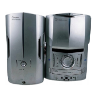
Do you have a question about the Pioneer XC-IS21T and is the answer not in the manual?

Pioneer XC-IS21T Specifications

General IconGeneral
Speaker Type2-way bass reflex
CD PlayerYes
Tape PlayerNo
Remote ControlYes
Signal-to-Noise Ratio80 dB
Power SupplyAC 220-240V, 50/60Hz
ConnectivityUSB
TunerFM/AM
Frequency Response20 Hz - 20 kHz

Summary

Safety Information

Exploded Views and Parts List

Front Panel Assembly (Part 1)

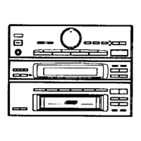
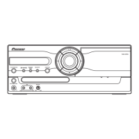
Exploded view of the front panel assembly, first part.

CD Mechanism Assembly

Exploded view and parts list for the CD mechanism assembly.

Deck Mechanism Unit (Part 1)

Exploded view and parts list for the first half of the deck mechanism unit.

Deck Mechanism Unit (Part 2)

Exploded view and parts list for the second half of the deck mechanism unit.

Block Diagram and Schematic Diagram

Block Diagram

Visual representation of the system's functional blocks and signal flow.

Overall Connection Diagram

Diagram showing interconnections between major system modules.

Tuner Section

FM Tuner Section Adjustment

FM tuner adjustment procedures and specifications.

AM Tuner Section Adjustment

AM tuner adjustment procedures and specifications.

U-COM and LCD Assemblies

CD and CD Motor Assemblies

CD Assembly PCB Layout

PCB layout and components for the CD assembly.

CD Motor Assembly PCB Layout

PCB layout and components for the CD motor assembly.

Deck Assembly

Deck Assembly PCB Layout

PCB layout and components for the Deck Assembly.

Tuner Module

PCB Parts List

F CD Assembly Parts

Deck Assembly Parts

Adjustment

Deck Section Adjustment

Procedures for adjusting deck section performance including playback and recording.

Playback Section Adjustments

Procedures for adjusting tape speed, head azimuth, and playback level.

Recording Section Adjustments

Procedures for adjusting recording bias and recording level.

Tuner Section Adjustment

FM Tuner Section

FM tuner adjustment procedures and specifications.

AM Tuner Section

AM tuner adjustment procedures and specifications.

Diagnosis

Disassembly Instructions

Step-by-step guide for disassembling the unit's main sections.

Sequence After Power On

Describes the operational sequence after the unit is powered on.

Single Operation Method

Method for performing single operations using test equipment.

Specifications

Amplifier Section Specifications

Technical specifications for the amplifier's power output and performance.

FM Tuner Section Specifications

Technical specifications for the FM tuner's frequency range and sensitivity.

AM Tuner Section Specifications

Technical specifications for the AM tuner's frequency range and sensitivity.

Compact Disc Player Section Specifications

Specifications for the CD player's type, usable discs, and wow/flutter.

Cassette Deck Section Specifications

Specifications for the cassette deck's system, heads, motor, and tape type.

Related product manuals