BEFORE SERVICING, REFER TO PAGE 3 AND 4 OF THIS DOCUMENT FOR IMPORTANT NOTICES
15 L22-405
1. Auto Filter Board Heat Circuit: Refer to Figure 6. Verify the auto lter
board has DC voltage by checking for the ashing green led (LED7). If
the LED is not ashing, then no DC power is present.
To check the heat circuit of the auto lter board (Lower le corner):
1. Verify the Le AC Power LED is lit, located just above the fuse. If the AC
LED is not lit, verify 24VAC - 28VAC at J1, blue wire to white wire. This
voltage comes straight from the transformer. If no voltage, troubleshoot
the transformer. If voltage is present, verify the fuse is good.
2. On J136, verify that either a jumper is installed, or if two white wire,
unplug J136 and check the white wires for connuity. If no connuity on
the white wires, check the oat switch operaon. Also ensure
jumpers are installed on J129 and J18.
3. Turn the controller on. Verify 24VAC - 28VAC on J32, yellow wire to
white wire. If present, connue to step 4.
a. If no voltage is present, verify that the LEFT SIDE ON LED is
lit.
I. If lit, the relay board is bad and needs to be replaced.
II. If the LEFT SIDE ON LED is not lit, check that the jumper
is installed properly on J18 and that the oat switch is
in the closed (up) posion. You can verify this by
following step 2 above.
III. If the LEFT SIDE ON LED is sll not lit, either the
Auto Filter Board, Controller or Commlink cable has
failed. No electrical tesng exists for this failure.
Swap one component at a me with a known working
component to determine the failure.
4. Check the J32 connector from brown/white wire to white wire for 24VAC
- 28VAC. If present, the safety (side on) contactor should be closed.
Connue to step 5.
a. If no voltage is present, try to reset the hi limit.
b. If no voltage is present aer reseng the hi limit, either the hi
limit has failed or a wire connecon issue is present.
5. With the controller calling for heat (LED next to thermometer on
controller is lit), verify 24VAC - 28VAC on J32, red wire to white wire. If
voltage is present, the cycling (heat demand) contactor should be closed.
The heat circuit is complete and the elements should be energized.
a. If no voltage is present, verify the LEFT HEAT DEMAND LED is lit
on the auto lter board. If the LED is lit, the relay has failed and
the auto lter board must be replaced.
b. If the LEFT HEAT DEMAND LED is not lit, either the Auto Filter
Board, Controller or Commlink cable has failed. No electrical
tesng exists for this failure. Swap one component at a me
with a known working component to determine the failure.
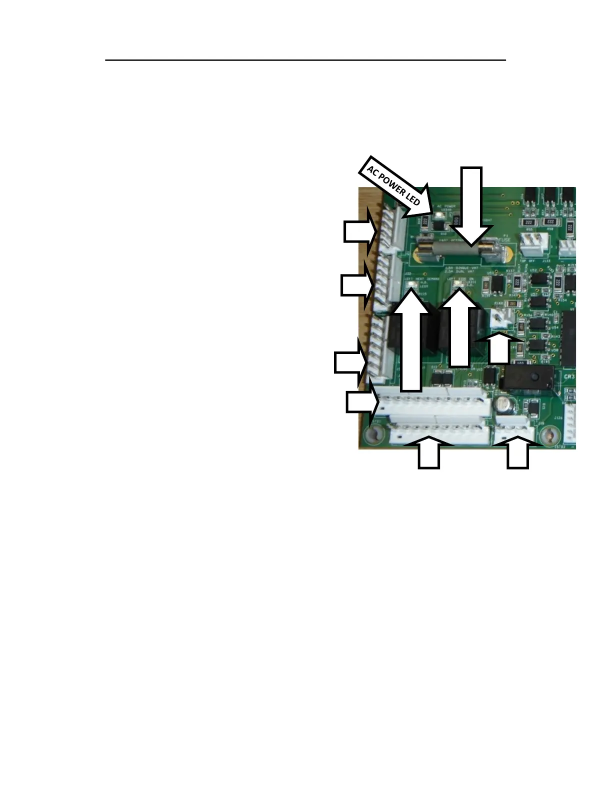
COMPONENT TROUBLESHOOTING (CONTINUED)
Figure 6
J18
J136
HEAT DEMAND LED
SIDE ON LED
FUSE 2.5A FA
J1
J32
J34
J129
J128