BEFORE SERVICING, REFER TO PAGE 3 AND 4 OF THIS DOCUMENT FOR IMPORTANT NOTICES
L22-405 RO 16
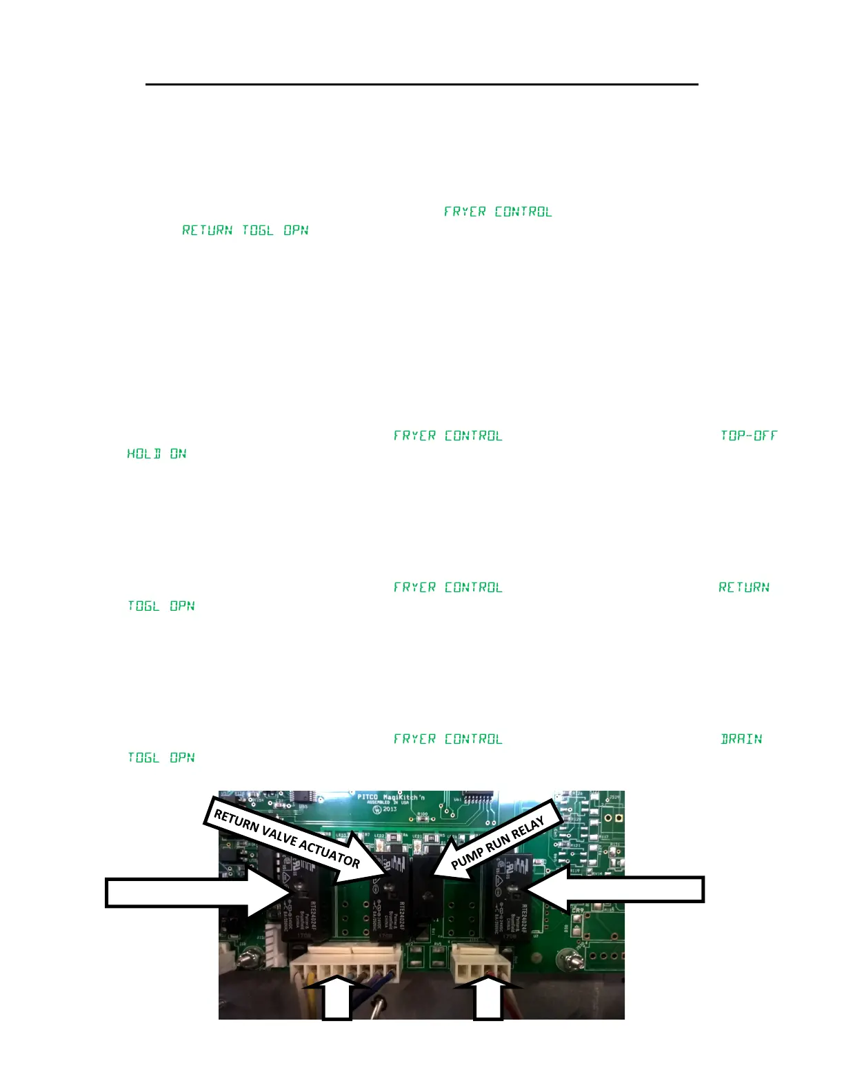
Auto Filter Board Filter Circuits: Refer to Figure 7. Verify the auto lter board has DC voltage by checking for the ashing green led (LED7). If the
LED is not ashing, then no DC power is present.
• Pump Run Relay (Relay board above lter pump only):
1. To test the operaon of the pump run relay, you need to perform a resistance check as this relay receives power input from the
connector rather than the auto lter board.
a. Remove the J127 connector.
b. On the controller, press and hold the lter key unl “ ” is displayed. Then press the “L” key and
“ ” will be displayed. At this point, pressing the “6” key will turn the pump run relay on and
pressing the “6” key again will turn the pump run relay o.
c. Using a mulmeter set to ohms, ohm out pin one and two on J127 directly on the relay board. With the LED above the
relay o, the mulmeter will display “O.L.” or “OPEN”.
d. Press the “6” key on the controller to acvate the pump run relay and turn on the LED above the relay. The mulmeter
should display 0.5Ω or less.
e. Turn the controller o and then plug in J127 when nished tesng the relay.
• Divert Actuator Relay (Relay board above lter pump only):
To test the operaon of the Divert Actuator Relay, turn o the lter motor circuit breaker then locate J127. With a mulmeter set
to DC Volts, place the meter’s posive lead in the white wire connector and the negave lead in the yellow wire connector.
With the LED above the divert actuator relay o, the meter should display a posive 24VDC.
On the controller, press and hold the lter key unl “ ” is displayed. Then press the “2” key and “
” will be displayed. At this point, pressing and holding the “6” key will turn on the divert actuator relay, return relay and
pump run relay. The meter display will change to negave 24VDC. Release the “6” key to turn o the pump run relay, close the
return valve and place the divert actuator back into the home posion. Turn on the lter motor circuit breaker.
• Return Actuator Relay:
To test the operaon of the Return Actuator Relay, turn o the lter motor circuit breaker then locate J127. With a mulmeter set
to DC Volts, place the meter’s posive lead in the light blue wire connector and the negave lead in the brown wire connector.
With the LED above the return actuator relay o, the meter should display a posive 24VDC.
On the controller, press and hold the lter key unl “ ” is displayed. Then press the “L” key and “
” will be displayed. At this point, pressing the “6” key will turn on the return relay and pump run relay. The meter
display will change to negave 24VDC. Release the “6” key to turn o the pump run relay and close the return valve.
• Drain Valve Relay: DRAIN THE TANK OF ALL LIQUIDS OR MAKE SURE THE FILTER PAN IS IN PLACE AND EMPTY BEFORE TESTING THE DRAIN
VALVE
To test the operaon of the Drain Actuator Relay, locate J138. With a mulmeter set to DC Volts, place the meter’s posive lead in
the red wire connector and the negave lead in the black wire connector.
With the LED above the drain actuator relay o, the meter should display a posive 24VDC.
On the controller, press and hold the lter key unl “ ” is displayed. Then press the “1” key and “
” will be displayed. At this point, pressing the “6” key will turn on the drain relay and open the drain valve. The meter
display will change to negave 24VDC. Press the “6” key again to turn o the drain actuator relay and close the drain valve.
COMPONENT TROUBLESHOOTING (CONTINUED)
DIVERT ACTUATOR RELAY
J138
J127
DRAIN VALVE ACTUATOR
Figure 7