+1 (603) 225-6684 L22-405 R0
hp://www.pitco.com 1 4/18
TROUBLESHOOTING AND
SERVICE MANUAL
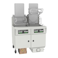
Covering SELVRF
Disclaimer: By performing any service on the intended equipment of this manual, you agree to assume all risks involved with performing the service including but not limited to damage to
property, personal injury and loss of income. Pitco/Magikitch’n/Anets/Perfect Fry recommends all service to be performed by a qualied service agent. Improper service or maintenance
can cause serious property damage, personal injury or death. It is the responsibility of the person servicing the equipment to follow all safety procedures and verify proper operaon of the
equipment aer performing service. Read the operaons manual prior to operang or servicing any equipment. Ensure to review all noces, cauons, warnings and dangers noted in the
operaons manual.