Do you have a question about the Pitney Bowes DI425 Series and is the answer not in the manual?
Provides information for installation and site repair of the DI380/DI425/SI3300/SI3500 Inserter.
Details that the manual applies to the sheet feeder and its accessory equipment for tabletop systems.
Lists operating guides for DI380, DI425, SI3300, and SI3500 models in various languages.
Outlines the manual's organization into sections covering introduction, specs, theory, procedures, OMR, troubleshooting, maintenance, and diagrams.
Explains warning, caution, and important messages used throughout the manual for safety.
Provides guidelines to protect sensitive equipment from static damage and general electrical safety precautions.
Details sheet feeder, insert feeder, and envelope feeder sizes, paper weights, and fold type thickness limits.
Covers physical dimensions, noise level, electrical requirements, maximum speed, and compliance for the machines.
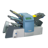
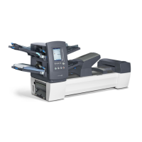
Provides an overview of the DI380/SI3300 and DI425/SI3500 folding/inserting machines and their basic operation.
Explains the operational sequence for feeding a single sheet with or without an insert into an envelope.
Describes the process of feeding an insert into an envelope, including double detection and collation.
Details the operation of feeding two sheets from sheet feeder 1 into an envelope.
Explains the sequence when a single sheet and an insert are fed into an envelope.
Describes the operation of feeding two sheets and an insert into an envelope.
Explains the operation when only folding is performed, without envelope insertion.
Details the process of accumulating sheets from the main feeder into an envelope.
Explains the function and scan areas of the double detect sensors for various feeder types.
Describes the AC motor operation, including capacitor start and solid-state relays.
Step-by-step instructions for removing machine covers and the logic board (PCB).
Procedure for removing the jam access plate, including disconnecting the DDD sensor.
Instructions for removing the sheet feeder separator roller and pad assembly.
Guide for removing the carriage assembly, including holding plates and screws.
Detailed steps for removing the lower collation roller, involving multiple components.
Instructions on how to remove the upper insert drive rollers and related parts.
Procedure for removing and replacing the fold rollers, including spring details.
Step-by-step guide for dismantling the insert feeder specific to the DI380 model.
Instructions for dismantling the insert feeder specific to the DI425/SI3500 models.
Guide for removing the top assembly of the machine, involving motors and drive belts.
Steps for removing envelope feed rollers and separator pad for DI380/SI3300 models.
Instructions for removing the envelope feeder for DI425/SI3500 models.
Steps for removing envelope feed rollers and separator pad for DI425/SI3500 models.
Guide for removing the flapper assembly and blade, including springs and screws.
Procedure for removing the transport pivot plate and insertion roller.
Instructions for removing the sealer rollers, including springs and belts.
Steps for removing the inverter motor assembly, accessing motor and encoder board.
Guide for removing conveyor transport belts and rollers, including tensioner and shields.
Instructions for removing lower flapper rollers, including pulleys and bearings.
Procedure for removing the lower envelope drive roller and associated parts.
Steps for removing the power supply unit and AC motor, including capacitors and wiring.
Instructions for adjusting the side guides in the envelope feed tray for DI380/SI3300.
Procedure to adjust the envelope feed bias left or right for DI425/SI3500 models.
Guide for centering the envelope separator pad relative to the separator rollers.
Instructions for adjusting the separator pad height for DI380/SI3300 models.
Procedure to adjust the separator pad height for DI425/SI3500 models.
Adjusting the hold down solenoid to set the flipper actuation height.
Adjusting the limit stop screw for the insertion hold down finger rest position.
Adjusting the transport plate end float and insertion springs for free pivoting movement.
Procedure to set the transport plate to achieve correct flag position in the sensor.
Setting fold plate offsets to match actual fold panel sizes to display dimensions.
Adjusting the nesting constant to set the timing of insert firing into a folded sheet.
Covers Q Station alignment, calibration, and height adjustments.
Guides for separator roller alignment, height, and pre-feed height adjustments.
Procedure to set skew adjustment for squarely folding skewed documents.
Instructions for adjusting the flapper blade to touch spacers, ensuring proper resistance.
Introduces OMR sensors, paper size adjustability, and feeder roles for OMR marks.
Defines OMR mark thickness, paper weight, envelope thickness, paper width, and clear zone requirements.
Explains OMR code structure, including fixed marks, data marks, and groups for different fold types.
Describes Basic OMR functionality for collating multi-page documents without mailpiece integrity checks.
Defines the benchmark mark as mandatory for all sheets within an OMR code.
Explains the safety mark's role in mailpiece integrity and calculating code length.
Details the BOC and EOC marks indicating the beginning and end of a sheet set.
Explains parity marks for error checking and how the machine handles detected errors.
Describes retiming marks for reliable code reading due to paper speed variations.
Illustrates allowable mark combinations for Basic OMR in collated sets.
Covers Enhanced OMR features like selective feed, auto-batch, and wrap-around sequencing for mailpiece integrity.
Explains Auto-Batch mode for stopping runs at predefined points or identifying special handling.
Details how to specify supplementary sheets or inserts using Select Feed marks.
Describes OMR marks for implementing sequential counts to detect missing or misplaced sheets.
Explains the WAS marks and their interpretation for counting sheets in a sequence.
Provides instructions for enabling Basic OMR and Enhanced OMR features.
References a scanning template document for OMR sensor setup and calibration.
Step-by-step guide for manually adjusting OMR sensor sensitivity using a set-up sheet.
Instructions on how to access the service menu and navigate its options.
Details the parameters menu for changing NVM settings, including Final Assembly Number.
Guides for testing machine components like sensors, motors, and interlocks via the control panel.
Provides general information and guidance for using troubleshooting charts and logic tests.
Lists error codes, operator checks, service diagnostics, and connector tests for fault resolution.
Overview of servicing procedures at 100k and 200k cycle intervals, emphasizing sensor cleaning.
Checklist for 100,000 cycle service, including checks on material, operation, safety, and component cleaning.
Checklist for 200,000 cycle service, including replacement of key components like pads and rollers.
Instructions for unpacking, positioning, leveling, and initial setup of the machine.
Guidance for training operators on machine layout, functions, job selection, and material loading.
Additional training points for supervisors, focusing on job programming and fine-tuning.
Illustrates the flow of material through the machine for DI380/SI3300 and DI425/SI3500 models.
Diagrams showing the physical locations of sensors, motors, and solenoids on the machine.
Lists test levels for mechanical switches, barrier switches, and reflective sensors.
Diagram showing the layout of the Printed Circuit Board (PCB) with connector and component labels.
Illustrates the routing of drive belts for the machine from front and rear views.
Schematic diagram for the insertion, moistener, and exit areas, showing wiring and components.
Schematic diagram for sheet feeders and collation motor, showing wiring and sensors.
Schematic diagram for fold plates and half fold mechanism, including motors and interlocks.
Schematic for the envelope feeder and AC hand crank, showing wiring and sensors.
Schematic of the P40 connector for the envelope platform on DI425/SI3500 models.
Schematic of the P41 connector for the envelope platform motor on DI425/SI3500 models.
Schematic diagram for the insert feeder, showing motors, sensors, and connectors.
Schematic diagram for the display and power supply unit (PSU), including AC motor connections.
| Type | Document Inserting System |
|---|---|
| Input Voltage | 120 VAC |
| Envelope Feeder Capacity | 250 envelopes |
| Document Sizes | Up to 8.5 x 14 inches |
| Folding Types | C-fold, Z-fold, half-fold |
| Maximum Envelope Size | 6.375" x 9.5" |
| Minimum Envelope Size | 3.5" x 6" |