ENGLISH (Translated from Italian) ENGLISH (Translated from Italian) ENGLISH (Translated from Italian) ENGLISH (Translated from Italian) ENGLISH (Translated from Italian) ENGLISH (Translated from Italian)
TABLE OF CONTENTS
A CONFORMITY
A.1
DECLARATION OF CONFORMITY (94/9/CE, Annex X, le. B)
A.2 DECLARATION OF CONFORMITY (2004/108/EC)
A.3 DECLARATION OF CONFORMITY IECEX
B MACHINE AND MANUFACTURER IDENTIFICATION
C GENERAL WARNINGS
D SAFETY INSTRUCTIONS
D.1 SAFETY WARNINGS
D.2 DEFINITION OF CLASSIFIED ZONES
D.3 INTENDED USE
D.4 FIRST AID RULES
D.5 GENERAL SAFETY RULES
D.6 PACKAGING
D.7
PACKAGE CONTENTS/PRE-INSPECTION
E BECOMING ACQUAINTED WITH K24
E.1 COMPATIBLE LIQUIDS
E.2 DISPLAY LCD
E.3 DISPLAY POSITIONING (METER VERSION ONLY)
E.4 USERS BUTTONS
F OPERATING MODES
G INSTALLATION
H DAILY USE
H.1 DISPENSING IN NORMAL MODE
H.1.1 PARTIAL RESET (NORMAL MODE)
H.1.2 RESETTING THE RESET TOTAL
H.2 DISPENSING WITH FLOW RATE MODE DISPLAY
H.2.1 PARTIAL RESET (FLOW RATE MODE)
I CALIBRATION
I1 DEFINITIONS
I2 CALIBRATION MODE
I.2.1 DISPLAY OF CURRENT CALIBRATION FAC-
TOR
AND RESTORING FACTORY FACTOR.
I.2.2 IN FIELD CALIBRATION
I.2.2.1
IN-FIELD CALIBRATION PROCEDURE
I.2.3 DIRECT MODIFICATION OF K FACTOR
L METER CONFIGURATION
M MAINTENANCE
N MALFUNCTIONS
O DISPOSAL
P TECHNICAL DATA
Q EXPLODED VIEWS AND OVERALL DIMENSIONS
A CONFORMITY
A.1 DECLARATION OF CONFORMITY
(2014/34/UE, Annex X)
The manufacturer: PIUSI S.p.A.
Via Pacinoi, 16/A z.i. Rangavino
46029 Suzzara (MN) Italy
Declares under its own and sole responsibility that the machine:
Type: K24
Model: F00408N*nn
(*N = X : Meter version ; N = Y : Pulser version)
Year of manufacture: refer to the year of production shown on the CE plate affixed to
the product.
comply with all relevant provisions of the following directives:
- 2014/34/UE
and the following harmonized standards, applied standards and/or technical specifica-
tions:
EN 60079-0:2012 ; IEC 60079-0:2011
EN 6007911-0:2012 / A11:2013 ; IEC 60079-11:2011
Notified body data: name, identification number and address
· 1 Name: CESI S.p.A.
· 2 Identification number: 0722
· 3 Address: Via Rubaino, 134 - 20134 - Milano
Number of the EC type-examination certificate: CESI 13 ATEX 049 X
This equipment is classified as follows:
II 2 G Ex ia IIB T4 (135°C) Gb
Read the Use and Maintenance manual before using the meter.
Suzzara, 20/04/2016 Oo Varini
Legal Representative
A.2 EC DECLARATION OF CONFORMITY (2014/30/EU)
The undersigned: PIUSI S.p.A.
Via Pacinoi, 16/A z.i. Rangavino
46029 Suzzara (MN) Italy
HEREBY STATES
under its own responsibility, that the equipment described below:
Descriprion: METER
Model: K24
Serial number: refer to Lot Number shown on CE label affixed to product Year of manu-
facture: refer to the year of production shown on the CE label affixed to the product is
in conformity with the legal provisions indicated in the directives :
- Electromagnetic Compatibility Directive 2014/30/EU
The documentation is at the disposal of the competent authority following motivated
request at Piusi S.p.A. or following request sent to the email address: doc_tec@piusi.com.
The person authorised to compile the technical file and draw up the declaration is Oo
Varini as legal representative.
Suzzara, 20/04/2016 Oo Varini
legal representative.
A.3 DECLARATION OF CONFORMITY IECEX
The manufacturer:: PIUSI S.p.A.
Via Pacinoi, 16/A z.i. Rangavino
46029 Suzzara (MN) Italy
Declares under its own and sole responsibility that the machine:
Type: K24
Model: F00408N*nn
(*N = X : Meter version ; N = Y : Pulser version)
Year of manufacture: refer to the year of production shown on the CE plate affixed to
the product.
comply with all the following harmonized standards, applied standards and/or technical
specifications:
IEC 60079-0:2011; IEC 6 0079-11:20 11
Notified body data: name, identification Number and address
· 1 Name: CESI S.p.A.
· 2 Identification number: 0722
· 3 Address: Via Rubaino, 134 - 20134 - Milan
CoC Certificate Number: IECEX CES 13.0021X
The equipment is classified as follows:
Ex ia IIB T4 (135°C) Gb
Read the Use and Maintenance manual before using the pump.
Suzzara, 20/04/2016 Oo Varini
Legal Representative
B MACHINE AND MANUFACTURER
IDENTIFICATION
AVAILABLE MODELS: K24
MANUFACTURER: PIUSI S.p.A. ,
Via Pacinotti 16/A – z.i. Rangavino
46029 Suzzara - Mantova (Italy)
C GENERAL WARNINGS
Important pre-
cautions
To ensure operator safety and to protect the meter from po-
tential damage, workers must be fully acquainted with this
instruction manual before performing any operation.
Symbols used
in the manual
The following symbols will be used throughout the manual
to highlight safety information and precautions of particular
importance:
WARNING
WARNING indicates a hazardous situation which, if not
avoided, could result in death or serious injury
NOTICE
NOTICE is used to address pratices not related to per-
sonal injury
Manual pres-
ervation
This manual should be complete and legible throughout. It
should remain available to end users and specialist installa-
tion and maintenance technicians for consultation at any
time.
Reproduction
rights
This manual belongs to Piusi S.p.A., which is the sole propri-
etor of all rights indicated by applicable laws, including, by
way of example, laws on copyrights. All the rights deriving
from such laws are reserved to Piusi S.p.A.: the reproduction,
including partial, of this manual, its publication, change, tran-
scription and notification to the public, transmission, includ-
ing using remote communication media, placing at disposal
of the public, distribution, marketing in any form, translation
and/or processing, loan and any other activity reserved by
the law to Piusi S.p.A..
WARNING
Installation, assembly and maintenance operations of
the K24, must only be performed by personnel qualified
to operate in HAZARDOUS LOCATIONS ZONE1.
BEFORE PROCEEDING WITH THE REFUELLING
OF THE AIRCRAFT, ENSURE THAT THE SYSTEM IN-
TENDED FOR SUCH ACTION COMPLIES WITH THE
REGULATIONS IN FORCE IN THE COUNTRY OF USE
Stop operation immediately if static sparking occurs
or if you feel a shock. Do not use equipment until you
identify and correct the problem.
Keep a working fire extinguisher in the work area.
Do not operate the unit when fatigued or under the in-
fluence of drugs or alcohol.
Do not alter or modify equipment. Alterations or modi-
fications may void agency approvals and create safety
hazards.
Keep children and animals away from work area.
Comply with all applicable safety regulations.
D SAFETY INSTRUCTIONS
D.1 SAFETY WARNINGS
WARNING
Mains - preliminary checks before installation
You must avoid any contact between the electrical
power supply and the fluid that needs to be FILTERED.
MAINTENANCE CONTROL
Before any checks or maintenance work are carried
out, disconnect the power source.
FOR YOUR SAFETY, REVIEW THE MAJOR WARNINGS AND CAUTIONS BE-
LOW BEFORE OPERATING YOUR METER
When metering flammable liquids, observe precau-
tions against fire or explosion
When handling hazardous liquids, always follow the
liquid manifacturer’s safety precautions
Always dispose of used cleaning solvents in a safe
manner according to the solvent manifacturer’s in-
structions.
During meter removal, liquid may spill. Follow the
liquid manifacturer’s safety precautions to clean up
minor spills
Do not blow compressed air through the meter
Do not allow liquids to dry inside the meter
Use only liquids permied
D.2 DEFINITION OF CLASSIFIED ZONES (EN60079-10-1)
FOREWORD
Definition of zones as shown in directive 99/92/CE
ZONE 0
Place where an explosive atmosphere made up of a mix of air and in-
flammable substances in the form of gas, vapour or mist is continuously
present, either for long periods or frequently.
Note: Generally speaking, said conditions, when they occur, involve the
inside of tanks, pipes and containers, etc.
ZONE 1
Place where it is probable that an explosive atmosphere, made up of
a mix of air and inflammable substances in the form of gas, vapour or
mist, can occur occasionally during normal operation.
Note: Said zone can also include:
- places in the immediate vicinity of zone 0;
- places in the immediate vicinity of supply openings;
- places in the immediate vicinity of filling and and emptying openings;
-
places in the immediate vicinity of appliances, protection systems and
fragile glass and ceramic components, or components made of other simi-
lar materials;
- places in the immediate vicinity of inadequately sealed stuffing boxes,
e.g., on pumps and valves with stuffing box.
ZONE 2
Place where it is improbable that an explosive atmosphere, made up
of a mix of air and inflammable substances in the form of gas, vapour
or mist, can occur during normal operation, but which, if it does occurs,
only persists for a short time.
Note: Said zone can include, among others, places surrounding the zones
0 or 1.
ZONE 20
Place where an explosive atmosphere in the form of a cloud of com-
bustible powders in the air is continuously present, either for long pe-
riods or frequently.
Note: Generally speaking, said conditions, when they occur, involve the
inside of tanks, pipes and containers, etc.
ZONE 21
Place where it is probable that an explosive atmosphere, in the form of a
cloud of combustible powders in the air, can occur occasionally during nor-
mal operation.
Note: Said zone can include, for example, among others, places in the
immediate vicinity of powder loading and emptying points and places
where powder layers form or which, during normal operation, could
produce an explosive concentration of combustible powders mixed
with the air.
ZONE 22
Place where it is improbable that an explosive atmosphere, in the form
of a cloud of combustible powders in the air, occur during normal op-
eration but which, if it does occur, only persists for a short time.
Note: This zone can comprise, among others, places near appliances,
protections systems and components containing powder, out of which
the powder can come out due to leaks with the formation of powder
deposits (e.g., milling salt, where the powder comes out of the mills and
deposits).
ZONE 1 ZONE 0
ZONE
20
ZONE 2
ZONE 21
ZONE 22
D.3 INTENDED USE
WARNING
INTENDED USE
METER FOR TRANFERRING FUEL SUITABLE FOR
OPERATING IN ZONES CLASSIFIED“1”AND “2”, AC-
CORDING TO DIRECTIVE 99/92/CE
THE DETERMINATION OF THE AREAS (ZONES) IS TO
BE CARRIED OUT BY THE USER
FORBIDDEN USE
Using the appliance for fluids other than those listed
at paragraph “COMPATIBLE LIQUIDS” and for uses
other than those described at the item “authorised use”
is forbidden.
PLANT OPERATION RESTRICTIONS IT IS FORBIDDEN:
1
To use the appliance in a construction configuration
other than that contemplated by the manufacturer
2
To use the appliance with fixed guards tampered with
or removed.
3
To use the appliance in places where there is risk of
explosion and/or fires classified in the following zones:
0; 20; 21; 22
4
To integrate other systems and/or equipment not con-
sidered by the manufacturer in the executive project.
5
To connect the appliance up to energy sources other
than those contemplated by the manufacturer
6
To use the commercial devices for purposes other than
those indicated by the manufacturer.
7
Do not use in case of lightnings
D.4 FIRST AID RULES
Contact with
the product
In the event of problems developing following EYE/SKIN
CONTACT, INHALATION or INGESTION of the treated
product, please refer to the SAFETY DATA SHEET of the
fluid handled.
NOTICE
Please refer to the safety data sheet for the product
SMOKING
PROHIBITED
When operating the dispensing system and in particular dur-
ing refuelling, do not smoke and do not use open flame.
WARNING
When metering flammable liquids, observe precau-
tions against fire or explosion
When handling hazardous liquids, always follow the
liquid manifacturer’s safety precautions.
Do not submerge the meter
D.5 GENERAL SAFETY RULES
Essential pro-
tective equip-
ment charac-
teristics
Wear protective equipment that is:
suited to the operations that need to be performed;
resistant to cleaning products.
Personal pro-
tective equip-
ment that must
be worn
Wear the following personal protective equipment during
handling and installation:
safety shoes;
close-fiing clothing;
protective gloves;
safety goggles;
instruction manual
Protective
equipment
WARNING
If handling hazardous liquids, always follow the Liquid
Manifacturer’s Safety Precautions. Wear protective
clothing such as goggles, gloves and respirator as in-
structed.
When metering flammable liquids, observe precautions
against fire or explosion. Do not meter in the presence
of any source of ignition including running or hot en-
gines, lighted cigarees, or gas or electric heaters
D.6 PACKAGING
FOREWORD
K24 comes packed in a cardboard box with a label indicating the
following data:
1 - contents of the
package
2 - weight of the
contents
3 - description of the
product
D.7
PACKAGE CONTENTS/PRE-INSPECTION
NOTICE
In the event that one or more of the components de-
scribed below are missing from inside the package,
please contact Piusi S.p.A. technical support.
Check that the data on the plate correspond to the de-
sired specifications. In the event of any anomaly, con-
tact the supplier immediately, indicating the nature of
the defects. Do not use equipment which you suspect
might not be safe.
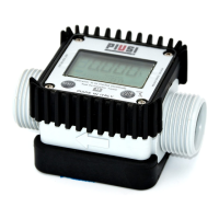
E BECOMING ACQUAINTED WITH K24
FOREWORD
Electronic digital meter featuring a turbine measurement system, de-
signed for precise measuring of low viscosity uids.
K24 is a bi-directional meter with LCD display and calibration
buons. The body is made of aluminum (conductive) and de-
signed for high flow 120 l/min. (32 GPM).
WARNING
Do not use K24 for purposes other than those intended.
E.1 COMPATIBLE LIQUIDS
Turbine
measurement
system
The turbine is placed inside a hole through the body of k24, fied with
M-f threaded inlet and outlet.
The liquids compatible with k24 are at low viscosity, namely:
COMPATIBLE
LIQUIDS
- DIESEL - KEROSENE
- PETROL - PETROL ALCOHOL MIXED MAX 20% (E20)
- AVGAS 100/100LL - JET A / A1
- ASPEN 2 / 4
WARNING
DO NOT USE WITH SUNDRIES LIQUIDS
INTENDED USE
The K24 ow meter has been designed and made for
the precise measurement of pumped liquids, including
under high pressure. Use only the liquids listed under the
item «Compatible liquids».
UNINTENDED USE Using the system for purposes other than those intend-
ed and indicated under “Intended use” is strictly forbid-
den.
All other uses excepting those for which the litre coun-
ter was designed and described in this manual shall be
deemed “MISUSE”, and consequently Piusi S.p.A. dis-
claims all liability for any injury caused to persons of
animals or damage to things or the system itself.
NOT COMPATIBLE
LIQUIDS
The K24 flow meter IS NOT compatible with the follow-
ing fluids :
All fluids of group IIC , IC (definition like IEC60079-0)
Not suitable with explosive dust (IIIC)
All fluids not suitable with alluminum, PA (polyammide) ,
PBT (Polybutylene terephthalate).
Main components K24
1
LCD display
3
CAL key
2
RESET key
4
Technical data plate
5
Marking
METER PULSER
E.2 DISPLAY LCD (METER VERSION ONLY)
FOREWORD
The “LCD” of the METER features two numerical registers and vari-
ous indications displayed to the user only when the applicable func-
tion so requires.
1 Partial register (5 figures with moving
comma FROM 0.1 to 99999) indicating
the volume dispensed since the reset
buon was last pressed
6 Indication of type of total, (TOTAL /
Reset TOTAL);
2 Indication of baery charge 7 Indication of unit of measurement of
Totals: L=Litres Gal=Gallons
3 Indication of calibration mode 8 Indication of Flow Rate mode
4 Totals register (6 figures with moving
comma FROM 0.1 to 999999), that
can indicate two types of Total:
4.1.
General Total that cannot be reset
(TOTAL)
4.2. Reseable total (Reset TOTAL)
9 Indication of unit of measurement of
Partial: Qts=Quarts Pts=Pints
L=Litres Gal=Gallons
5 Indication of total multiplication factor
(x10 / x100)
4
5
6
9
7
1
2
3
8
E.3 DISPLAY POSITIONING (METER VERSION ONLY)
FOREWORD
The square shape of the k24 body allows the card to be rotated in its
housing, thus ensuring great versatility in positioning
This allows easy display readings in any position. The card housing is
closed by a plastic cover sealed through a rubber protection acting as
a gasket as well. This can be easily removed unscrewing the 4 screws
that fix both the cover and the card (1).
NOTICE
While fixing the K24 card, make sure the baery con-
tact cable is not placed above the circular housing of
the bulb.
E.4 USERS BUTTONS
FOREWORD
The METER features two buons (RESET and CAL) which individu-
ally perform two main functions and, together, other secondary func-
tions
.
MAIN
FUNCTIONS
PERFORMED
- for the RESET key, reseing the partial register and Reset Total
- for the CAL key, entering instrument calibration mode
SECONDARY
FUNCTIONS
Used together, the two keys permit entering configuration mode
where the desired unit of measurement can be set.
LEGEND CALIBRATE MEANS PERFORMING ACTIONS ON THE METER
KEYS. BELOW IS THE LEGEND OF THE SYMBOLS USED TO
DESCRIBE THE ACTIONS TO BE PERFORMED
SHORT
PRES
SURE
OFCAL
KEY
CAL
LONG
PRES
SURE
OFCAL
KEY
CALCAL
CAL
SHORT
PRES
SURE
OF
RESET
KEY
RESET
LONG
PRES
SURE
OF
RESET
KEY
RESET
RESET
RESET
F OPERATING MODES
OPERATING
MODES
The user can choose between two different operating modes:
The meter features a non-volatile memory for storing the dispensing
data, even in the event of a complete power break for long periods.
The measurement electronics and the LCD display are fied in the top
part of the K24 which remains isolated from the fluid-bath measure-
ment chamber and sealed from the outside by means of a cover.
1 - Normal
Mode
Normal Mode: Mode with display of Partial and Total dispensed quanti-
ties
2 - Flow rate
Mode
Flow Rate Mode: Mode with display of Flow Rate, as well as Partial dis-
pensed quantity.
G INSTALLATION
WARNING
Installation, assembly and maintenance operations of
the K24 , must only be performed by personnel quali-
fied to operate in HAZARDOUS LOCATIONS ZONE1.
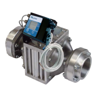
K24 features a threaded, perpendicular inlet and outlet
(1” NPT or BSP male and female that can be combined
together). It has been designed to be easily installed
in any position: fixed in-line or mobile on a dispensing
nozzle. In order to improve the life of the turbine, it is
recommended to fit a strainer before the meter itself
For installations on system, position meter so that the
baery housing can be easily reached.
CONNECTIONS To protect against the leakage, make sure all threads
are sealed with two or three turns of thread tape or a
sealing compound compatible with the liquid being
metered
Make sure the thread tape or sealing compound does
interfere with flow
Make sure there are no leaks in the connections.
To seal leaks, remove and inspect the meter and replace
the thread tape or sealant. Refer to the Troubleshooting
Section
To minimize static electricity build up,use only static
conductive hose R<1MΩm when metering flammable
fluids, and keep the fill nozzle in contact with the con-
tainer being filled during the filling process.
All parts of our system must be incontinuity and
grounded.
DO NOT exceed 145 psi - 20 bar line pressure.
DO NOT install additional foot valve or check valve
without a pressure relief valve; otherwise the meter
may rapture.
PULSER
CONNECTIONS
The electrical signal between K24 PULSER and the
control unit device must be protected by intrinsically
safe barrier.
The electrical limits of signal are the follows :
Ui = 12 V
Ii = 100 mA
Pi = 0.3 W
The barier must be properly connected to an earth
grounded.
Improper installation of this meter and barier could re-
sult in death or serious injury.
H DAILY USE
FOREWORD
The only operations that need to be done for daily use are partial
and/or reseable total register reseing. The user should use only
the dispensing system of K24. Occasionally the meter may need to
be configured or calibrated. To do so, please refer to the relevant
chapters.
Below are the two typical normal operation displays. One display page shows the partial
and reset total registers. The other shows the partial and general total. Switchover from
reseable total to general total display is automatic and tied to phases and times that are
in factory set and cannot be changed.
NOTICE
6 digits are available for Totals, plus two icons x 10 /
x100. The increment sequence is the following:
0.0 -> 99999.9 -> 999999 -> 100000 x 10 -> 999999 x 10
->100000 x 100 -> 999999 x 100
H.1 DISPENSING IN NORMAL MODE
FOREWORD
Normal mode is the standard dispensing. While the count is made,
the partial and reseable total are displayed at the same time (reset
total).
NOTICE
Should one of the keys be accidentally pressed during
dispensing, this will have no effect.
stand by
A few seconds aer dispensing has ended, on the lower register, the
display switches from reseable total to general total: the word reset
above the word total disappears, and the reset total is replaced by
the general total. This situation is called standby and remains stable
until the user operates the k24 again.
H.1.1 PARTIAL RESET (NORMAL MODE)
The partial register can be reset by pressing the reset key
when the meter is in standby, meaning when the display screen
shows the word “TOTAL”.
Aer pressing the reset key, during reset, the display screen
first of all shows all the lit-up digits and then all the digits that
are not lit up.
At the end of the process, a display page is first of all shown
with the reset partial and the reset total
and, aer a few moments, the reset total is replaced by the non
reseableTotal.
H.1.2 RESETTING THE RESET TOTAL
The reset total reseing operation can only be performed
aer reseing the partial register. The reset total can in fact
be reset by pressing the reset key at length while the display
screen shows reset total as on the following display page:
Schematically, the steps to be taken are:
1 Wait for the display to show normal standby display page
(with total only displayed)
2 Press the reset key quickly
3 The meter starts to reset the partial
4 While the display page showing the reset total is displayed
Press the reset key again for at least 1 second
The display screen again shows all the segments of the
display followed by all the switched-off segments and fi-
nally shows the display page where the reset Reset Total
is shown.
H.2 DISPENSING WITH FLOW RATE MODE DISPLAY
It is possible to dispense fluids, displaying at the same time::
1 the dispensed partial
2 the Flow Rate in [Partial Unit / minute] as shown on the
following display page:
Procedure for entering this mode:
1 wait for the Remote Display to go to Standby, meaning the
display screen shows Total only
2 quickly press the CAL key.
3 Start dispensing
The flow rate is updated every 0.7 seconds. Consequently, the display could be relatively
unstable at lower flow rates. The higher the flow rate, the more stable the displayed
value.
NOTICE
The flow rate is measured with reference to the unit of
measurement of the Partial. For this reason, in case of
the unit of measurement of the Partial and Total be-
ing different, as in the example shown below, it should
be remembered that the indicated flow rate relates to
the unit of measurement of the partial. In the example
shown, the flow rate is expressed in Qts/min.
The word “Gal” remaining alongside the flow rate re-
fers to the register of the Totals (Reset or NON Reset)
which are again displayed when exiting from the flow
rate reading mode.
To return to “Normal” mode, press the CAL key again. If one of the two keys RESET or
CAL is accidentally pressed during the count, this will have no effect.
NOTICE
Even though in this mode they are not displayed, both
the Reset Total and the General Total (Total) increase.
Their value can be checked aer dispensing has termi-
nated, returning to “Normal” mode, by quickly pressing
CAL.
H.2.1 PARTIAL RESET (FLOW RATE MODE)
To reset the Partial Register, finish dispensing and wait for
the Remote Display to show a Flow Rate of 0.0 as indicated
in the illustration
then quickly press RESET
I CALIBRATION
When operating close to extreme use or flow rate conditions (close to minimum or maxi-
mum acceptable values), an on-the-spot calibration may be required to suit the real condi-
tions in which the K24 is required to operate.
I.1 DEFINITIONS
CALIBRATION
FACTOR OR
“K FACTOR”
Multiplication factor applied by the system to the electrical pulses
received, to transform these into measured fluid units.
FACTORY K
FACTOR
Factory-set default factor. It is equal to 1,000. This calibration factor
ensures utmost precision in the following operating conditions:
Fluid Diesel
Temperature: 20°C - 68°F
Flow rate: 50 lit/min (13 GPM)
Even aer any changes have been made by the user, the factory k
factor can be restored by means of a simple procedure.
USER K FAC-
TOR:
Customized calibration factor, meaning modified by calibration.
I.2 CALIBRATION MODE
Why calibrate? 1
Display the currently used calibration factor:
2
Return to factory calibration (Factory K Factor) aer a pre-
vious calibration by the user
3
Change the calibration factor using one of the two previ-
ously indicated procedures
FOREWORD Two procedures are available for changing the Calibration
Factor:
1
In-Field Calibration, performed by means of a dispensing operation
2
Direct Calibration, performed by directly changing the calibration
factor
In calibration mode, the partial and total dispensed quantities indicated on the display screen
take on different meanings according to the calibration procedure phase. In calibration mode,
the K24 cannot be used for normal dispensing operations. In “Calibration” mode, the totals
are not increased
NOTICE
The K24 features a non-volatile memory that keeps
the data concerning calibration and total dispensed
quantity stored for an indefinite time, even in the
case of a long power break; aer changing the bat-
teries, calibration need not be repeated.
II 2 G
Atex
CES 13.0021X
K24
ELECTRONIC
ALLUMINIUM
TURBINE
METER
Use, maintenance and Calibration manual
En
Bulletin M0320 A EN_00