ENGLISH (Translated from Italian) ENGLISH (Translated from Italian) ENGLISH (Translated from Italian) ENGLISH (Translated from Italian) ENGLISH (Translated from Italian) ENGLISH (Translated from Italian) ENGLISH (Translated from Italian)
I.2.1 DISPLAY OF CURRENT CALIBRATION FACTOR
AND RESTORING FACTORY FACTOR.
CALCAL
CAL
By pressing the CAL key while the appli-
ance is in Standby, the display page ap-
pears showing the current calibration fac-
tor used. If no calibration has ever been
performed, or the factory seing has been
restored aer previous calibrations, the
following display page will appear:
The word “Fact” abbreviation for “factory”
shows that the factory calibration factor is
being used
If, on the other hand, calibrations have
been made by the user, the display page
will appear showing the currently used
calibration factor ( in our example 0,998) .
The word “user” indicates a calibration fac-
tor set by the user is being used..
CAL
The flow chart alongside
shows the switchover logic
from one display page to
another
In this condition, the Reset
key permits switching from
User factor to Factory fac-
to r.
To confirm the choice of
calibration factor, quickly
press CAL while “User” or
“Fact” are displayed.
Aer the restart cycle, the
K24 uses the calibration
factor that has just been
confirmed
CAL
CALCAL
CAL
RESET
RESET
TIME OUT
NOTICE
When the Factory Factor is confirmed, the old User
factor is deleted from the memory
I.2.2 IN FIELD CALIBRATION
FOREWORD
This procedure calls for the fluid to be dispensed into a graduated
sample container in real operating conditions ( flow rate, viscosity,
etc.) requiring maximum precision.
NOTICE
For correct K24 calibration, it is most important to:
1
When the Factory Factor is confirmed, the old User factor is deleted
from the memory
2
use a precise Sample Container with a capacity of not less than 5
litres, featuring an accurate graduated indicator.
3
ensure calibration dispensing is done at a constant flow rate equiva-
lent to that of normal use, until the container is full;
4
Not reduce the flow rate to reach the graduated area of the con-
tainer during the final dispensing stage (the correct method during
the final stages of sample container filling consists in making short
top-ups at normal operation flow rate);
5
aer dispensing, wait a few minutes to make sure any air bubbles are
eliminated from the sample container; only read the Real value at the
end of this stage, during which the level in the container could drop.
6
Carefully follow the procedure indicated below.
I.2.2.1 IN-FIELD CALIBRATION PROCEDURE
ACTION DISPLAY
1
NONE
Meter in Standby
2
CALCAL
CAL
LONG CAL key keying
The Meter enters calibration mode, shows <<CAL>> and displays
the calibration factor in use instead of partial. The words “Fact” and
“USER” indicate which of the two factors (factory or user) is currently
in use.
Important: This factor is that which the instrument also uses for field
calibration measurement operations
3
RESET
RESET
RESET
LONG RESET key keying
The Meter shows “CAL” and the partial at zero. The Meter is ready to
perform in-field calibration.
4
DISPENSING INTO SAMPLE CONTAINER
Without pressing any key, start dispensing into the sample container
Dispensing can be interrupted and started again at will. Continue
dispensing until the level of the fluid in the sample container has
reached the graduated area. There is no need to reach a preset
quantity.
Indicated value Real value
5
RESET
SHORT RESET key keying
The Meter is informed that the calibration dispensing operation is
finished.
Make sure dispensing is correctly finished before performing this
operation. To calibrate the Meter, the value indicated by the partial
totaliser (example 9.800) must be forced to the real value marked
on the graduated sample container. In the boom le part of the
display an arrow appears (upwards and downwards), that shows the
direction (increase or decrease) of the value change displayed when
the following operations 6 or 7 are performed.
6
RESET
SHORT RESET key keying
The arrow changes direction. The operation can be repeated to
alternate the direction of the arrow.
7
CALCAL
CAL
CAL
SHORT/LONG CAL key keying
The indicated value changes in the direction indicated by the arrow
- one unit for every short CAL key keying
- continually if the CAL key is kept pressed. The speed increase rises
by keeping the key pressed. If the desired value is exceeded, repeat
the operations from point (6).
8
RESET
RESET
RESET
LONG RESET key keying
The Meter is informed that the calibration procedure is finished.
Before performing this operation, make sure the INDICATED value is
the same as the REAL value.
Indicated value Real value
The Meter calculates the new USER K FACTOR ; this calculation
could require a few seconds, depending on the correction to be made
ATTENTION: If this operation is performed aer action (5), without
changing the indicated value, the USER K FACTOR would be the
same as the FACTORY K FACTOR, thus it is ignored.
9
NO OPERATION
At the end of the calculation, the new USER K FACTOR is shown
for a few seconds, aer which the restart cycle is repeated to finally
achieve standby condition.
IMPORTANT: From now on, the indicated factor will become the
calibration factor used by the Meter and will continue to remain
such even aer a baery change
10
NO OPERATION
The Meter stores the new work calibration factor and is ready
to begin dispensing, using the USER K FACTOR that has just
been calculated.
.
I.2.3 DIRECT MODIFICATION OF K FACTOR
If normal Meter operation shows a mean percentage error, this can be corrected by
applying to the currently used calibration factor a correction of the same percent-
age. In this case, the percentage correction of the USER K FACTOR must be calcu-
lated by the operator in the following way
New cal. Factor = Old Cal Factor *
( )
100 - E%
100
Example:
Error percentage found: E% - 0.9 %
CURRENT calibration factor: 1.000
New USER K FACTOR: 1.000 * [(100 – ( - 0.9))/100] = 1.000 * [(100 + 0.9)/100] =
1.009
If the Meter indicates less than the real dispensed value (negative error) the new cali-
bration factor must be higher than the old one as shown in the example. The opposite
applies if the Meter shows more than the real dispensed value (positive error).
ACTION DISPLAY
1 NONE
METER in Standby.
2
CALCAL
CAL
LONG CAL KEY KEYING
Meter enters calibration mode, shows “CAL” and displays the
calibration factor being used instead of the partial. The words “Fact”
and “User” indicate which of the two factors (factory or user) is
currently being used.
3
RESET
RESET
RESET
LONG RESET KEY KEYING
The Meter shows “CAL” and the zero partial total.
Meter is ready to perform in-field calibration by dispensing – see
previous paragraph.
4
RESET
RESET
RESET
LONG RESET KEY KEYING
We now go on to Direct change of the calibration factor: the word
“Direct” appears together with the Currently Used calibration factor.
In the boom le part of the display, an arrow appears (upwards or
downwards) defining the direction (increase or decrease) of change
of the displayed value when subsequent operations 5 or 6 are
performed.
5
RESET
SHORT RESET KEY KEYING
Changes the direction of the arrow. The operation can be repeated to
alternate the direction of the arrow.
6
CALCAL
CAL
CAL
SHORT/LONG CAL KEY KEYING
The indicated value changes in the direction indicated by the arrow
- one unit for every short CAL key keying
- continually if the CAL key is kept pressed. The speed increase rises
by keeping the key pressed. If the desired value is exceeded, repeat
the operations from point (5).
7
RESET
RESET
RESET
LONG RESET KEY KEYING
The Meter is informed that the calibration procedure is finished.
Before performing this operation, make sure the INDICATED value
is that required.
8 NO OPERATION
At the end of the calculation, the new USER K FACTOR is shown
for a few seconds, aer which the restart cycle is repeated to finally
achieve standby condition.
IMPORTANT: From now on, the indicated factor will become the
calibration factor used by the Meter and will continue to remain
such even aer a baery change
9 NO OPERATION
The Meter stores the new work calibration factor and is ready to
begin dispensing, using the USER K FACTOR that has just been
changed.
L METER CONFIGURATION
The METER feature a menu with which the user can select the main measurement
unit, Quarts (Qts), Pints (Pts), Litres (Lit), Gallons (Gal); The combination of the
unit of measurement of the Partial register and that of the Totals is predefined
according to the following table:
Combination no.
Unit of Measurement
Partial Register
Unit of Measurement
Totals Register
1 Litres (L) Litres (L)
2 Gallons (Gal) Gallons (Gal)
3 Quarts (Qts) Gallons (Gal)
4 Pints (Pts) Gallons (Gal)
To choose between the 4 available combinations:
1 Wait for the METER to go to Standby
2
CAL
RESET
+
Then press the CAL and RESET keys together. Keep these
pressed until the word “UNIT” appears on the screen to-
gether with the unit of measurement set at that time (in
this example Litres / Litres )
3 Every short press of the RESET key, the various combina-
tions of the units of measurements are scrolled as shown
below:
Gal
Qts
Pts
Gal
RESET
RESET
RESET
4
CALCAL
CAL
By pressing the CAL key at length, the new seings will be
stored, the METER will pass through the start cycle and
will then be ready to dispense in the set units.
NOTICE
The Reset Total and Total registers will be automati-
cally changed to the new unit of measurement.
NO new calibration is required aer changing the Unit of Mea-
surement.
M MAINTENANCE
BATTERY
REPLACEMENT
Use only Piusi Baery code *18021
WARNING
To reduce risk of ignition of a flammable or explosive
atmosphere do not use Volt meter or smiliar powered
tools during the live maintenance.
WARNING
The warranty and the safety of the product is insured
only with the use of baery Piusi code *18021 PIUSI
S.p.A. DENIES LIABILITY FOR DAMAGES CAUSED
BY THE USE OF BAT TERIES NOT SUITABLE.
K24 should be installed in a position allowing the bat-
teries to be replaced without removing it from the
system.
BATTERIES Check the baeries and terminals at least every year
to ensure proper operation. It is strongly recommend-
ed that terminals be cleaned annually
K24 features two low-baery alarm levels:
1
When the baery charge falls below the first level on the
LCD, the fixed baery symbol appears. In this condition,
K24 continues to operate correctly, but the fixed icon
warns the user that it is ADVISABLE to change the bat-
teries.
2
If K24 operation continues without changing the baer-
ies, the second baery alarm level will be reached which
will prevent operation. In this condition the baery icon
starts to flash and is the only one to remain visible on the
LCD.
WARNING
During meter removal, liquid may spill. Follow the liq-
uid manifacturer’s safety precautions for clean up of
minor spills.
TO REMOVE
BATTERY
1 Ensure all liquid is drained from the meter. This could
include draining the hose, meter, nozzle or pipe
2
Wear protective clothing as necessary, loosen both ends
of the meter. Use a wrench only on the meter’s flat metal
surfaces
3 If the meter is not immediately installed again, cap
the hose end or pipe to prevent spills
To reduce the risk of ignition of a flammable or explo-
sive atmosphere, baeries must only be changed in a
non-hazardous location
To prevent ignition of flammable or combustibile at-
mospheres, disconnect power before servicing
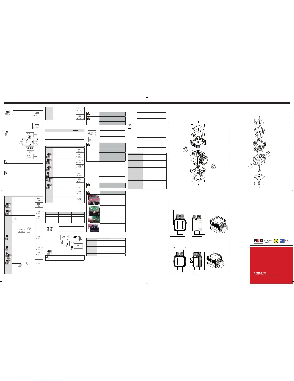
To change the
baeries, with
reference to
the exploded
diagram posi-
tions, proceed as
follows
1 Press RESET to update all the totals
2 Loosen the 4 fixing screws of the lower cover
3 Remove the old baeries and disconnect the plug
4
Place the new baeries in the same position as the old ones
(sure to put the baery in the correct way)
5 Close the cover again, by positioning the rubber protec-
tion as a gasket
6 K24 will switch on automatically and normal operation can
be resumed
The K24 will display the same Reset Total, the same Total and the same Partial
indicated before the baeries were changed. Aer changing the baeries, the
meter does not need calibrating again.
CLEANING
Only one operation is necessary to clean the k24. Aer
removing k24 from the plant where it was built in, any re-
sidual elements can be removed by washing or mechani-
cally-handling. If this operation does not restore a smooth
rotation of the turbine, it will have to be replaced.
WARNING
Do not discard the old baeries in the environment.
Refer to local disposal regulations.
Do not use compressed air onto the turbine in order to
avoid its damage because of an excessive rotation
TO STORE Follow the liquid manifacturer’s instructions for the
disposal of contaminated cleaning solvents
WARNING
K24 Front face replacement
1
Carefully remove the screws from the corners of the
front panel, and then carefully li the front cover up
away from the main body of the meter.
2
Carefully remove the screws from the corners of the
front panel, and then carefully li the front cover up
away from the main body of the meter.
3
When the new panel is fied make sure the power adapt-
er is fied correctly with the location pin in the correct
way
4
Carefully refit the display panel back onto the main
body making sure the wire is tucked into the corner
and replace the screws
N MALFUNCTIONS (EN60079-19)
Problem Possible cause Remedial Action
LCD: no indication
Bad baery contact Check baery contacts
Not enough mea-
surement precision
Wrong K FACTOR
With reference to paragraph H,
check the K FACTOR
The meter works below
minimum acceptable flow
rate.
Increase the flow rate until an ac-
ceptable flow rate range has been
achieved
Reduced or zero
flow rate
TURBINE blocked Clean the TURBINE
The meter does not
count, but the flow
rate is correct
Incorrect installation of
gears aer cleaning
Repeat the reassembly procedure
Possible electronic card prob-
lems
Contact your dealer
K24 is switched of
Baery discharged or in-
stalled in the wrong way
Check baery charge and/or
check the baery position
O DISPOSAL
Foreword
If the system needs to be disposed, the parts which make it up
must be delivered to companies that specialize in the recycling
and disposal of industrial waste and, in particular:
Disposing of
packing materials
The packaging consists of biodegradable cardboard which can be
delivered to companies for normal recycling of cellulose.
Metal Parts Dis-
posal
Metal parts, whether paint-finished or in stainless steel, can be
consigned to scrap metal collectors.
Disposal of elec-
tric and electron-
ic components
These must be disposed of by companies that specialize in the
disposal of electronic components, in accordance with the indica-
tions of directive 2012/19/CE (see text of directive below).
Informa-
tion re-
garding
the envi-
ronment
for clients resid-
ing within the Eu-
ropean Union
European Directive 2012/19/EC requires that all equipment
marked with this symbol on the product and/or packaging not
be disposed of together with non-differentiated urban waste.
The symbol indicates that this product must not be disposed of
together with normal household waste. It is the responsibility of
the owner to dispose of these products as well as other electric
or electronic equipment by means of the specific refuse collec-
tion structures indicated by the government or the local governing
authorities.
Disposing of RAEE equipment as household wastes is strictly for-
bidden. Such wastes must be disposed of separately.
Any hazardous substances in the electrical and electronic appli-
ances and/or the misuse of such appliances can have potentially
serious consequences for the environment and human health.
In case of the unlawful disposal of said wastes, fines will be ap-
plicable as defined by the laws in force.
Miscellaneous
parts disposal
Other components, such as pipes, rubber gaskets, plastic parts
and wires, must be disposed of by companies specialising in the
disposal of industrial waste.
P TECHNICAL DATA
Measurement system
TURBINE
Resolution (nominal)
0.010 lit/pulse 0.006 gall./pulse
Flow Rate (Range)
7 ÷ 120 (Lit/min) 2 ÷ 32 (gal/min)
Operating pressure (Max)
20 (Bar) 290 (psi)
Bursting pressure (Min)
100 (Bar) 1450 (psi)
Storage temperature (Range)
-20 ÷ + 70 (°C) -4 ÷ 158 (°F)
Storage humidity (Max)
95 (% RU)
Operating temperature
(Range)
-10 ÷ + 50 (°C) 14 ÷ 122 (°F)
Flow resistance
0.30 Bar at 100 lit/min. 4.35 psi a 26.41gal/min
Permissible Viscosity (Range)
2 ÷ 5.35 cSt/ pulse
Accuracy
1% aer calibration within
10÷90 (litres/min) 2,65÷23,8 (gallons/min) range
Reproducibility (Typical)
0,3 (%)
Screen
Liquid crystals LCD. Featuring:
- 5-figure partial
- 6-figure Reset Total plus x10 / x100
6-figure non reset Total plus x10 / x100
Power Supply
Lithium baery PIUSI code *18021
Baery life
24 months
Weight
0.4 Kg (included baeries)
Protection
IP65
Pulser Data
Ui = 12 V
Ii = 100 mA
Pi = 0.3 W
Q EXPLODED VIEWS AND OVERALL DIMENSIONS
METER PULSER
METER
46
1" NPT / BSP
113
76
59
PULSER
PG7
77
113
46
76
59
1" NPT / BSP
BULLETIN M0320 A EN _ 00
©Piusi S.p.A.
EN. This document has been drawn upwith the greatest
aention to precision and accuracy of all data herein contained.
Nevertheless, PIUSI S.p.A. denies liability for any possible
mistake or omission.
II 2 G
Atex
CES
13.0021X

 Loading...


