6/20
Pizzato Elettrica Srl
via Torino, 1
36063 MAROSTICA (VI)
ITALY
e-mail: info@pizzato.com
web site: www.pizzato.com
Phone: +39.0424.470.930
ZE FOG131C19-EU
1 INFORMATION ON THIS DOCUMENT
1.1 Function
The present operating instructions provide information on installation, connection and
safe use for the following articles: ST G••••••.
1.2 Target audience
The operations described in these operating instructions must be carried out by
qualified personnel only, who are fully capable of understanding them, and with the
technical qualifications required for operating the machines and plants in which the
safety devices are to be installed.
1.3 Application field
These operating instructions apply exclusively to the products listed in paragraph
Function, and their accessories
1.4 Original instructions
The Italian language version is the original set of instructions for the device. Versions
provided in other languages are translations of the original instructions.
2 SYMBOLS USED
This symbol indicates any relevant additional information.
Attention: Any failure to observe this warning note can cause damage or mal-
function, including possible loss of the safety function.
3 DESCRIPTION
3.1 Device description
The safety device described in these operating instructions is defined as a coded,
type-4 interlocking device without contact acc. to EN ISO 14119.
The safety sensors with RFID technology to which these operating instructions
refer are safety devices designed and implemented for the control of gates, guards,
enclosures, and doors in general, which are installed to protect dangerous parts of
machines without inertia.
3.2 Intended use of the device
- The device described in these operating instructions is designed to be applied on
industrial machines (as defined in the Machinery Directive) for state monitoring of
movable guards.
- The direct sale of this device to the public is prohibited. Installation and use must be
carried out by qualified personnel only.
- The use of the device for purposes other than those specified in these operating
instructions is prohibited.
- Any use other than as expressly specified in these operating instructions shall be
considered unintended by the manufacturer.
- Also considered unintended use:
a) using the device after having made structural, technical, or electrical modifications
to it;
b) using the product in a field of application other than as described in paragraph
TECHNICAL DATA.
4 INSTALLATION INSTRUCTIONS
Attention: Installing a protective device is not sufficient to ensure operator safety
or compliance with machine safety standards or directives. Before installing a protec-
tive device, perform a specific risk analysis in accordance with the key health and
safety requirements in the Machinery Directive. The manufacturer guarantees only the
safe functioning of the product to which these operating instructions refer, and not the
functional safety of the entire machine or entire plant.
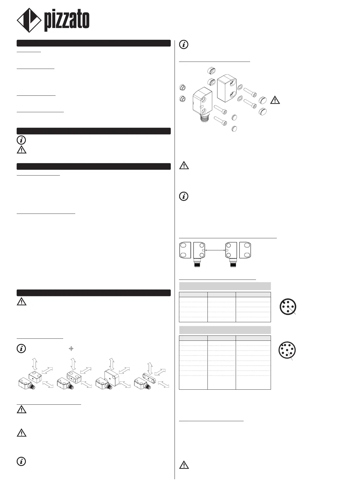
4.1 Actuation directions
The device can be actuated by approaching the actuator from any direction.
The centring symbols indicated on the device and actuator must face one
another when the guard is closed, regardless of actuation direction.
Article ST G••••••-G•T Article ST G••••••-D•T Article ST G••••••-E•T Article ST G••••••-L•T
4.2 Selection of the actuator type
Attention: The device is available with two types of RFID actuator: with high
(articles SM •1T) or low (articles SM •0T) level of coding. If the chosen actuator has
a low level of coding, the additional specifications given in Std. EN ISO 14119:2013
paragraph 7.2 must be applied during the installation.
Attention: If the chosen actuator has a low level of coding, any other low level
coded actuators present in the same place where the device has been installed must
be segregated and kept under strict control in order to avoid any bypassing of the
safety device. If new low level coded actuators are fitted, the original low level coded
actuators must be disposed of or rendered inoperable.
It is advisable to use high coding level actuators to make the installation safer
and more flexible. In this way, no device screening, installation in inaccessible zones
or other requirements specified by the Std. EN ISO 14119 for low coding level actua-
tors will be necessary.
The device can also be used in conjunction with the SM D•T, SM E•T, and SM L•T
actuators, with high or low coding level, and the safety levels will remain unaffected.
4.3 Fixing of the device and actuator
The sensor can be fixed in any po-
sition, by rotating it into the most
suitable direction so that the out-
puts of the connections face the
direction required by the applica-
tion in question.
Attention: Once you have de-
fined the sensor fixing direction, in-
sert the threaded sleeves provided
in the holes on the opposite side
to where the screws are inserted.
Always affix the sensor and actua-
tor with 2 M4 screws with resistance class 4.6 or higher, and flat seating heads. Install
the screws with medium resistance thread lock, and a number of threads engaged
equal to or greater than the screw diameter. The device or actuator must never be
fixed with less than 2 screws. Tightening torque of the M4 screws between 0.8 and
1.0 Nm.
Attention: As required by EN ISO 14119, the actuator must be fixed immovably
to the door frame.
For correct fixing, other means can also be used, such as rivets, non-removable se-
curity screws (one-way), or other equivalent fixing system, provided that it can ensure
adequate fixing.
Tamperproof safety caps are provided with the device. Inserting the caps is
considered a suitable measure, to reduce the possibility of actuator disassembly to a
minimum, in accordance with EN ISO 14119. Therefore, by applying the caps supplied
to the device, normal screws can be used to affix the actuator.
Do not use a hammer for the adjustments, unscrew the screws and adjust the device
manually, then tighten it in position.
4.4 Assembly of multiple sensor-actuator systems
50 mm
Where more than one safety device is in-
stalled to the same machine, the installation
distance between sensor and actuator sys-
tems must be at least 50 mm.
4.5 Electrical connections of the device
5-pole versions
ST G•2••••, ST G•6••••
M12 connector Cable Connection
1
42
3
5
1 brown
A1 (+)
2 white
OS1
3 blue
A2 (-)
4 black
OS2
5 grey
O3
(a)
8-pole versions
ST G•3••••, ST G•4••••, ST G•5••••, ST G•7••••, ST G•8••••
M12 connector Cable Connection
1
2
3
4
5
6
7
8
Notes
(a) inverted output for articles ST G•6••••,
ST G•7••••, ST G•8••••.
(b) for articles ST G•3••••, ST G•7••••.
(c) for articles ST G•4••••, ST G•8••••.
(d) for articles ST G•5••••.
1 white
A1 (+)
2 brown
IS1
3 green
A2 (-)
4 yellow
OS1
5 grey
O3
(a)
6 pink
IS2
7 blue
OS2
8 red
not connected
(b)
I3
(c)
EDM
(d)
Legend:
A1-A2 = supply I3 = programming input
IS1-IS2 = safety inputs O3 = signalling output
OS1-OS2 = safety outputs EDM = monitoring input external contactors
4.6 RFID sensor switching points
When the actuator is brought inside the safe activation zone (dark grey area), the sen-
sor enables the safety outputs (LED on, green).
When the actuator moves out of the safe zone, the sensor keeps the safety outputs
enabled and, via the yellow LED flashing, it indicates that the actuator is entering the
limit activation zone (light grey area).
When the actuator leaves the limit activation zone, the sensor disables the outputs
(LED on, yellow).
Attention: The device actuation/release distances can be influenced by the pres-
ence of conductive or magnetic material in the sensor vicinity. The working actuation
and release distances must always be checked following installation.
 Loading...