8/20
5.6 EDM connection (External Device Monitoring)
ST G•51•••
ST G•310••
ST G•310••
PLC
IS1
K1 K2
O3
SM ••TSM ••TSM ••T
O3
O3
EDM
+
+
IS2
OS1 OS2
IS1 IS2
IS1 IS2
OS1
OS2
OS1
OS2
For certain specific applications, as an
alternative to connection to safety mod-
ules, it is possible to use the ST G•51•••
article with check of the NC contacts of
the forcibly guided relays (K1, K2) con-
nected to the EDM input, installed as
the last sensor in the cascade.
5.7 Interfacing
Connections with CS AR-08•••• safety modules
Input configuration with monitored start
2 channels / Category 4 / up to SIL 3 / PL e
5-pole versions 8-pole versions
S33
S21 S22
S35
S34
A2
S52
S12
A1
-
+
OS2
A1
+
A2
-
ST
CS
OS1
S33
S21 S22
S35
S34
A2
S52
S12
A1
-
+
OS2
OS1
IS2
IS1
A1
+
A2
-
ST
CS
Connections with CS AR-05•••• / CS AR-06•••• safety modules
Input conguration with manual start (CS AR-05••••) or monitored start (CS AR-06••••)
2 channels / Category 4 / up to SIL 3 / PL e
5-pole versions 8-pole versions
S21 S22
S34
A2
A1
-
+
S52
S12
OS2
OS1
A1
+
A2
-
ST
CS
S21 S22
S34
A2
A1
-
+
S52
S12
OS2
OS1
IS2
IS1
A1
+
ST
CS
A2
-
Connections with CS AT-0••••• / CS AT-1••••• safety modules
Input configuration with monitored start
2 channels / Category 4 / up to SIL 3 / PL e
5-pole versions 8-pole versions
S33
S21 S22
S35
S34
A2
A1
-
+
S31
S12
OS2
OS1
A1
+
A2
-
ST
CS
S33
S21 S22
S35
S34
A2
A1
-
+
S31
S12
OS2
OS1
IS2
IS1
A1
+
A2
-
ST
CS
Connections with CS MF••••0, CS MP••••0 safety modules
The connections vary according to the program of the module
Category 4/ up to SIL 3 / PL e
5-pole versions 8-pole versions
OS2
OS1
A1
+
OS2
OS1
A1
+
A2
-
A2
-
ST ST
CS
OS2
OS1
IS2
IS1
A1
+
OS2
OS1
IS2
IS1
A1
+
A2
-
A2
-
ST ST
CS
Connections with external contactors (EDM versions only)
K1
K2
+
A1 IS1
OS1 OS2
IS2 A2
+
-
ST G•51•••
EDM
Articles ST G•5•••• must be connected
to contactors with forcibly guided output
contacts, as shown in the adjacent
diagram. When connected in this way,
the sensor can be classified as a control
circuit device up to PDF-M (EN 60947-
5-3)
Caution: if all OS safety outputs
are connected directly to a safety contac-
tor, we recommend using fast switching
diodes connected in parallel to the con-
tactor coils.
Connections with Pizzato Elettrica expansion modules (e.g. CS ME-03••••)
(only ST G•5•••• versions)
OS2
+
-
ST G•51•••
EDM
A2
A1
A2
IS2
IS1
OS1
OS2
OS1
EDMEDM
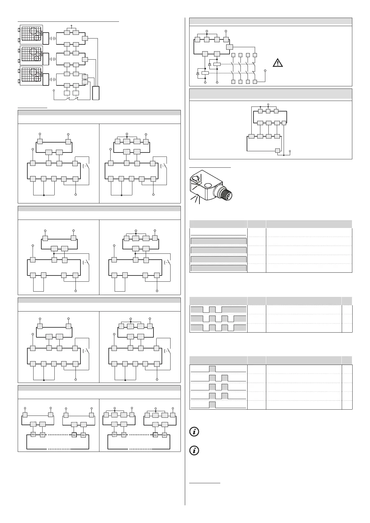
5.8 Operating states
The sensor has a multicolour signalling LED, which, through
the use of illumination, flashing, and colour sequences, indi-
cates the various device operating states to the user, as well
as any warnings or errors affecting internal electronic compo-
nents.
The LED can be seen on both sides of the sensor, regardless
of device installation direction.
The predefined sensor operating states (OFF, RUN, ERROR, SET) are indicated by
a constantly lit LED.
LED illumination sequence
Sensor
state
Description
OFF
Sensor off.
GN
RUN
Normal operating state with safety outputs on. No
pending error or warning.
YE
RUN
Normal operating state with safety outputs off. No
pending error or warning.
VT
SET
New actuator acquisition state.
RD
ERROR
Internal device error state.
Table 1: Predefined operating states
If an ERROR event is identified, the LED cycles between continuous light corresponding
to the ERROR state (see Table 1) with one of the illumination sequences listed in Table
2, each of which corresponds to a different message type.
LED illumination sequence
Sensor
state
Description
Prio-
rity
RD RD RD
ERROR
Temperature error: the sensor temperature is
outside permitted limits.
9
RD RD RD RD
ERROR
Voltage error: the sensor supply voltage is
outside permitted limits.
8
RD RD YE RD
ERROR
Short circuit between the safety outputs OS1
and OS2.
7
Table 2: ERROR messages
If a WARNING event is identified, the LED cycles between continuous light
corresponding to the current operating state (see Table 1) with the corresponding
illumination sequence listed in Table 3.
LED illumination sequence
Sensor
state
Description
Prio-
rity
RD
WARNING
Temperature warning: the sensor temperatu-
re is close to permitted limits.
6
RD RD
WARNING
Voltage warning: the supply voltage is close
to permitted limits.
5
YE YE
WARNING
No signal at the inputs IS1 and IS2.
4
YE GN
WARNING
Inputs IS1 and IS2 inconsistent.
3
YE
WARNING
The actuator is in the detection limit area.
2
Table 3: WARNING messages
Legend: GN = green RD = red YE = yellow
BU = blue VT = purple
WARNING events are generally reversible. ERROR events are not reversible:
the device does not recover from the error, but must be switched off, and the cause of
the error resolved prior to switching back on.
If multiple ERROR or WARNING events are present at the same time, the highest
priority error only is indicated. For example, where both a temperature warning and a
voltage warning are present, only the temperature signalling sequence is indicated;
the voltage warning sequence is indicated only once the temperature warning is no
longer active, i.e. the temperature exits the alert threshold.
5.9 Reset input
The following error states due to a failure external to the device can be rest using the
I3 input:
- a short circuit or overload of safety outputs (OS1, OS2),
- a short circuit between a safety output and the supply voltage.
Pizzato Elettrica
CS ME-03••••
expansion module
 Loading...