EasyManua.ls Logo

Planet 2.4GHZ DIGITALREMOTE CONTROL SYSTEM User Manual

Planet 2.4GHZ DIGITALREMOTE CONTROL SYSTEM
16 pages
To Next Page IconTo Next Page
Page #1 background imageLoading...
Page #1 background image
Planet
T5
2.4GHZ DIGITAL
REMOTE CONTROL SYSTEM
Instruction Manual
Includes*
Advanced 2.4GHz 5-channel professional transmitter
Advanced 2.4GHz micro 6-channel receiver
Features
Simple one-button transmitter/receiver binding
Side & rear ergonomic grips for maximum transmitter security
Steel carry handle and neck strap mount
Precision, adjustable height dual-axis stick units
Front-mounted reversing switch panel
Unique slow-rate retract/flap switch (channel 5)
Low power consumption 4-cell transmitter
Lightweight (6 gram) micro 6-channel receiver
Convenient crystal-free operation
*See box label for detailed contents listing
For use with Park Flyer, indoor aircraft
and small electric coaxial helicopter type models.
For use with recreational radio controlled model aircraft only.
Not a toy—suitable only for persons aged 14+.
rock-solid r/c
Planet
Question and Answer IconNeed help?

Do you have a question about the Planet 2.4GHZ DIGITALREMOTE CONTROL SYSTEM and is the answer not in the manual?

Planet 2.4GHZ DIGITALREMOTE CONTROL SYSTEM Specifications

General IconGeneral
BrandPlanet
Model2.4GHZ DIGITALREMOTE CONTROL SYSTEM
CategoryRemote Control
LanguageEnglish

Summary

Transmitter Features

Control Trims

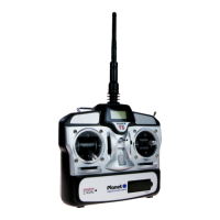
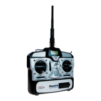
Fine trim the position of the servos on the transmitter.

Channel 5 Switch

Operates a servo at a slow rate for realistic deployment of spoilers, flaps, etc.

Battery Status LCD

Digital readout of transmitter voltage. Stop flying when voltage falls to 4.4V.

Reversing Switches

Reverse the direction of aileron, elevator, throttle, and rudder functions.

R6M Receiver

R6M Deployment

Securing and mounting the receiver in a model, aerial arrangement for optimal signal.

Receiver Connections

Details of pinouts for servo and battery/switch connections, stressing correct polarity.

Binding Transmitter to Receiver

Recognizing Unbound Receiver

How to identify if the receiver is not bound to the transmitter via LED status.

Binding Procedure

Step-by-step instructions for binding the transmitter and receiver.

Transmitter Usage

Transmitter Aerial Positioning

Guidance on optimal positioning of the transmitter aerial for signal strength.

Range and Power Check

Procedures for checking operational range and transmitter power levels before flight.

Operational Controls

Mode Change Switch

Switch to change transmitter stick layout between Mode 1 and Mode 2.

Failsafe Operation

Describes the failsafe function that sets throttle to zero and controls to center on signal loss.

Flight Control Modes

Transmitter Layouts

Illustrates transmitter stick layouts for Mode 1 (throttle right) and Mode 2 (throttle left).

Helicopter Mode 2 Controls

Details control assignments for helicopter flight in Mode 2.

Aircraft Mode 2 Controls

Details control assignments for aircraft flight in Mode 2.

Helicopter Mode 1 Controls

Details control assignments for helicopter flight in Mode 1.

Aircraft Mode 1 Controls

Details control assignments for aircraft flight in Mode 1.

Related product manuals