10
3.4 Connecting IPOE-175 to PD
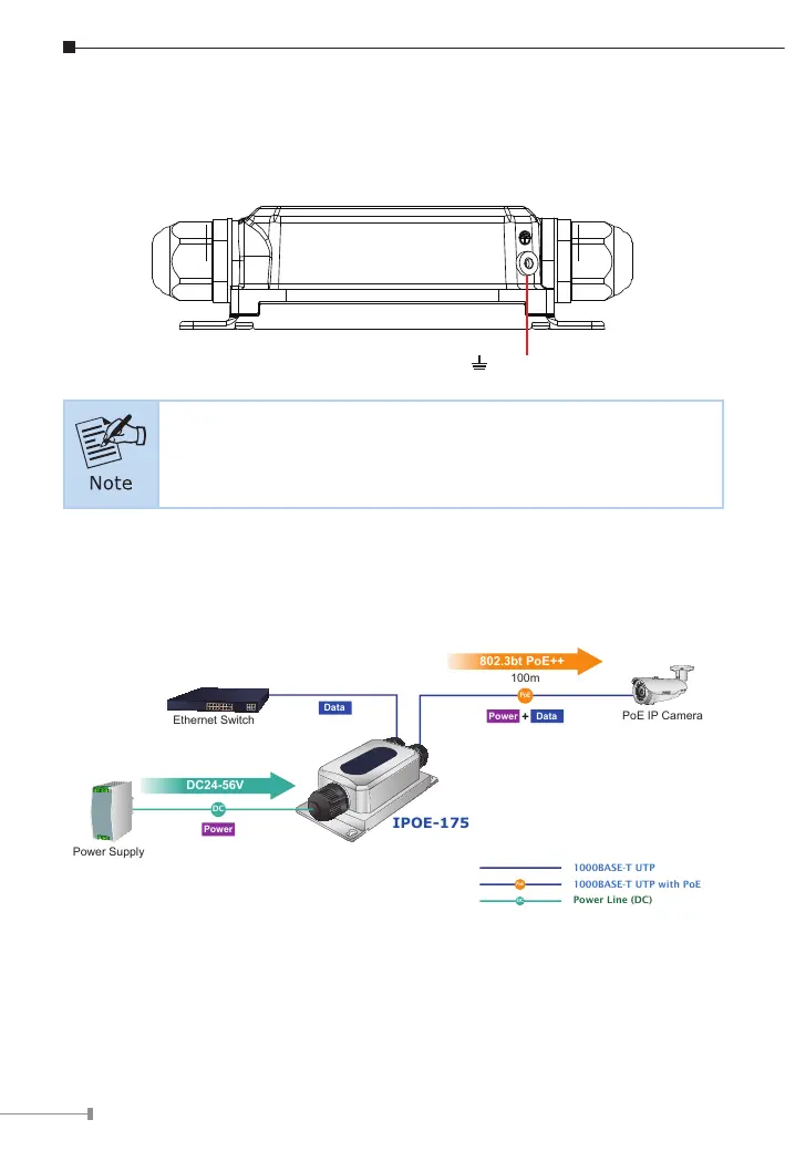
Users MUST complete grounding wired with the device; otherwise, a sudden
lightning could cause fatal damage to the device.
Earth Ground
EMD (Lightning) DAMAGE IS NOT COVERED UNDER WARRANTY.
3.5 Connecting IPOE-175 to PD
Step 1: Connect the additional Cat5e/6/6A cable from the PoE++ Out of the
IPOE-175 to a remote PD.
DC
Power Line (DC)
1000BASE-T UTP
PoE
1000BASE-T UTP with PoE
PoE
Power
Data
PoE IP Camera
IPOE-175
Data
100m
802.3bt PoE++
Power Supply
Power
DC
DC24-56V
Ethernet Switch
Step 2: The PoE++ Out port is the power injector which transmits DC
voltage to the Cat5e/6/6A cable and transfer data from the Data
source.