5
2.3 Data Input Port and 802.3bt PoE++ Output Port
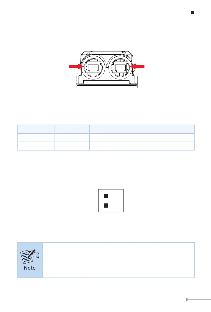
Figure 2-3 shows the data input port and PoE++ output port side of the IPOE-
175.
PoE++ Output Port Data Input Port
Figure 2-3: Two RJ45 Ports
2.4 LED Indicators
LED Color Function
PWR Green Indicates it has power.
PoE-in-Use Amber Indicates the port is providing power.
To install the 2-pin Terminal Block Connector on the Outdoor PoE Injector,
simply follow the following steps:
Step 1: Insert positive DC power wire into V+, negative DC power wire into
V-, and grounding wire into Ground.
V+
V
-
2-pin
Step 2: Tighten the wire-clamp screws for preventing the wires from
loosening and plug them into the Wall-mount Gigabit Ethernet Router
1. The wire gauge should be in the range from 20 to 22 AWG.
2. The device must be grounded.