20
Installation Instructions
Step 1. Connect the LRP Injector (LRP-101CH) and LRP Extender
(LRP-104CET) to ends of BNC terminated coaxial cable.
Stick the “Warning Sticker” on the coaxial cable.
Step 2. Connect Cat5/6 UTP cable to LRP-101CH and non-PoE switch or
workstation.
Step 3. Connect 48~56V DC power adapter to LRP-101CH power socket,
then the PWR LED of LRP-101CH and LRP-104CET should be lit up
immediately.
Step 4. Connect Cat5/6 UTP cable to LRP-104CET and IEEE 802.3at/af
complied PoE IP camera or PoE Wireless AP.
Note
1. PoE output capacity is based on different DC Power Input /
PoE Input.
2. The LRP-101CH has two power input options; only one mode
is available at one time. PoE power input cannot be used if
power input of DC 52V or 56V is selected.
Type 3 One LRP-822CS/LRP-1622CS with AC power input and one
LRP-104CET with PoE power output
The LRP Switch is powered via the AC power. The IEEE 802.3at/af compliant
PoE PD will automatically be powered by the LRP Extender via UTP.
P1 P2 Fault
PWR
LNK
LRP IN
4
3
2
1
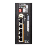
LRP-104CET
Ext.
PWR
10W 20W 30W 40W
PoE
Power
Usage
ACTLNK
PoE In-use
ON
ON
ON
ON
OFF
OFF
OFF
OFF
1
Port PoE
2
3
4
Long Reach PoE
Extender
1 2 3 4
OFF
P1 P2 Fault
PWR
LNK
LRP IN
4
3
2
1
LRP-104CET
Ext.
PWR
10W 20W 30W 40W
PoE
Power
Usage
ACTLNK
PoE In-use
ON
ON
ON
ON
OFF
OFF
OFF
OFF
1
Port PoE
2
3
4
Long Reach PoE
Extender
1 2 3 4
OFF
LRP-104CET
Long Reach PoE Extender
Remote LRP Power
PoE Power Budget
20 watts (max.)
110-240V AC
PoE
IP Camera
LRP-822CS
Power over Coaxial
802.3at PoE+
Up to 400m
Up to 400m
UTP
PoE
PoE
PoE
PoE
UTP
PoE
PoE
PoE
PoE
 Loading...