6
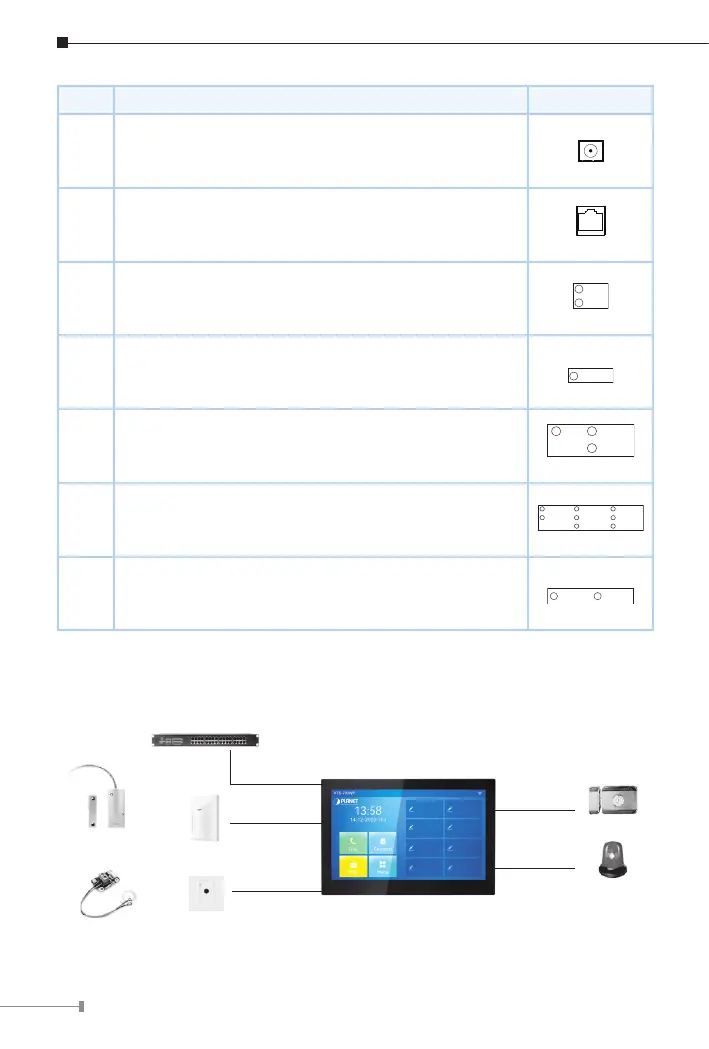
No. Description Interface
1 Power interface: 12V/1A input
2
10/100M adaptive RJ45 interface (It is recommended
to use CAT5 or CAT5e network cable.)
3-1 12V/1A input
3-2 1 doorbell interface
DB_IN1
3-3
3 short-circuit output interfaces can be connected to
electric locks, alarm, etc.
3-4
8 alarm input interfaces for connecting switches,
infrared sensor, door sensor, vibration sensors, etc.
ALM_IN_4
ALM_IN_5
ALM_IN_
3-5
2 RS485 interfaces connected to card reader, sensor,
etc. (Reserved for future use)
485_B 485_A
3.3 External Device Connection Diagram
Switch
Door Magnetic
Switch
WAN Port
Output Port
Output Port
Alarm light
Input Port
Input Port
Infrared Sensor
Emergency Key
Or
Or
Or