PLS SLD DETECTOR
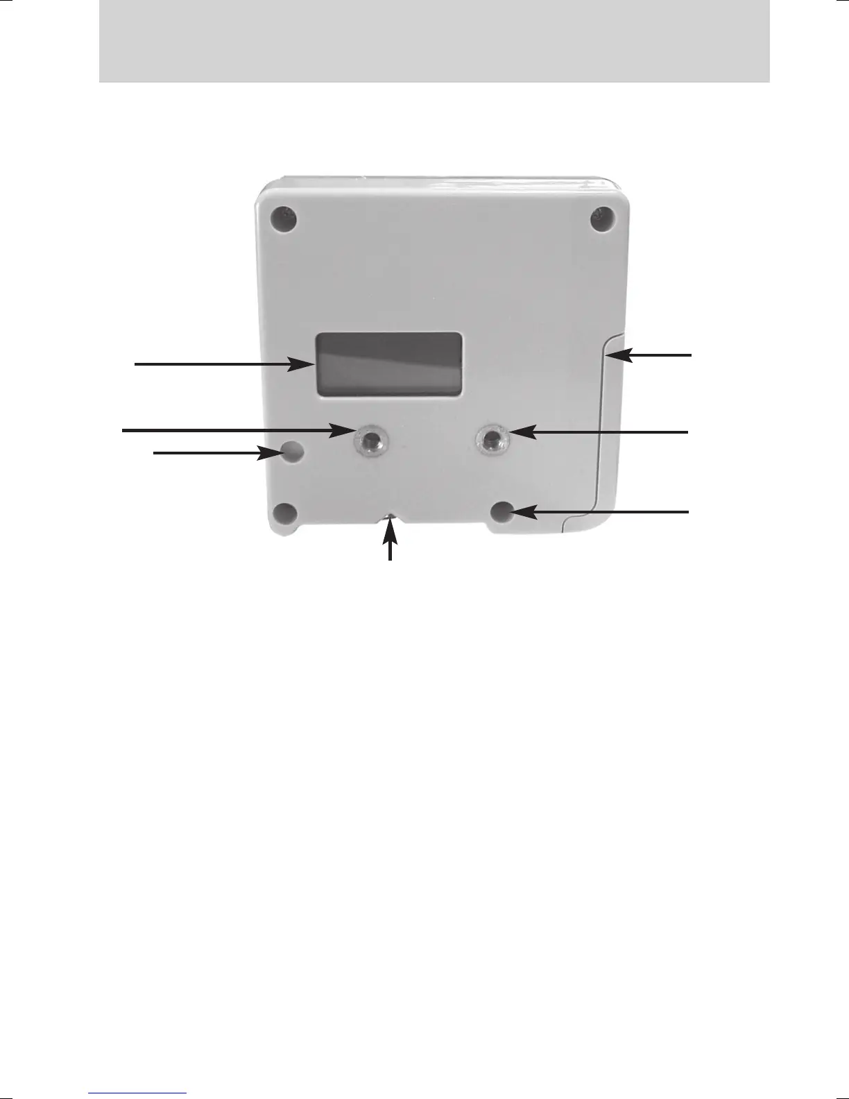
Operation - Back View
8. Captive Screw Thread - detector thread insert accepts the rod
clamp screw to secure detector to the clamp.
9. Offset Notch - used for transferring reference marks, 2” 3/32 from
top of detector.
10A & 10B. Clamp Guide - 2 dimples help align rod clamp.
10A- Vertical line reference. 10B- Horizontal line reference.
11. Battery Door Latch - depress latch to open and install or replace
batteries. Insert batteries noting plus (+) and minus (-) terminal dia-
gram on the detector housing. Compartment houses (1) 9 Volt battery.
Care- Do not submerge PLS SLD in water.
12. Rear LCD - functions the same as the front LCD.
12
8
10 A
9
8
11
10 B