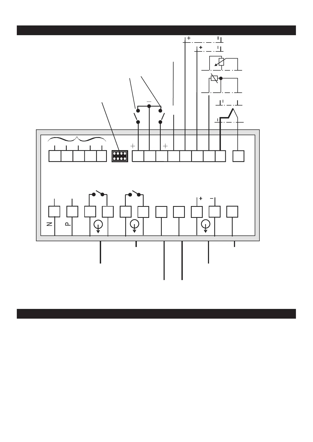
CONNECTIONS
0 ... 10V , 5V
Protective earth
0/4 ... 20 mA
Control inputs Transducer
Control output for
channel selector PT100,resistance
Connection to
interface module
(cable 9404 407 50011)
ß 1V
Thermo
couples
Mains
(230/115/24)
Limit contact
L2
2-wire transmitter
supply
Limit contact
L1
Analog output
Protective earth
The Digital 380 indicator is provided for installation in an enclosure. The electrical
safety is reached by correct installation in a control cabinet/panel.
ELECTRICAL CONNECTIONS
Keep mains cables separate from signal and measuring cables. We recommend
twisted and sceened measurung cables (screen connected to earth).
This ensures optimum interference suppression!
Connected final elements must be equipped with protective circuits to manufacturer
specification. This avoids voltage peaks which can cause trouble to the instrument.
The instruments must be protected by an individual or common fuse for a max.
power consumption of 8VA per unit (standard fuse ratings, min 1 A)!.
a
Signal and measurement circuits may carry max. 50 V r.m.s. against
ground,mains circuits may carry max. 250 V r.m.s. between terminals
9499-040-24701 3
+
+
0(4) ... 20mA
K
K
K
230/115/24V
16
15
14
13
12
9
8
7
6
5
4
3
2
1
+U
T
22
21
20
19
18
17
23
24
25
26
27
d1
L2
L1
d2
a
100%
0%