Connecting diagram for current measurement via voltage input
Channel selector switching outputs:
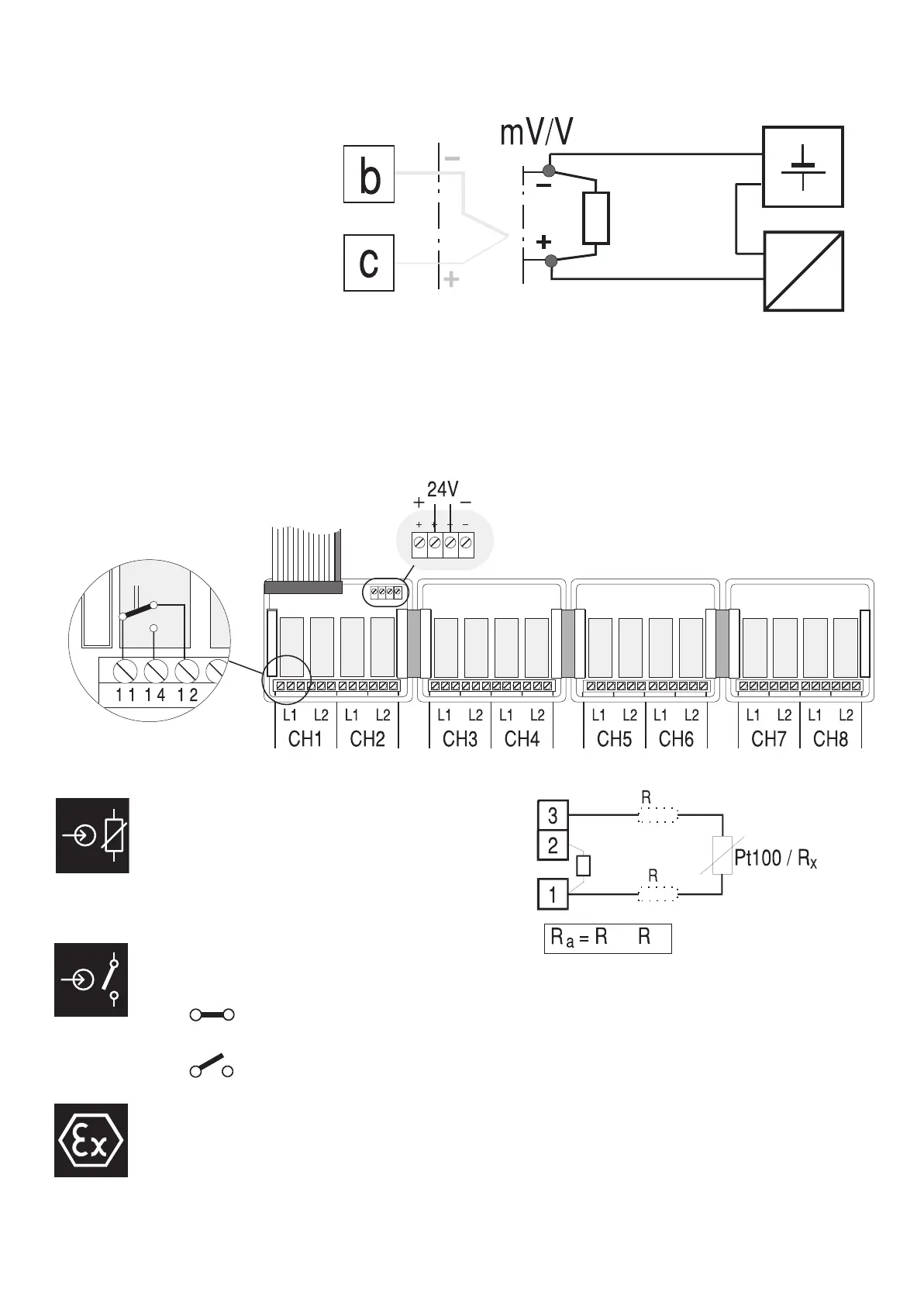
With connection of Pt100 and
potentiometric transducers in
2-wire circuit, lead resistance
adjustment (R
a)
is necessary.
Control inputs d1 and d2 are
suitable forpotential-free contacts or 0/5V - TTL signals.
0V = = Logic „1"
5V = = Logic „0"
The indicator must be protected via an external fuse. Connecting both
terminals 20,21 to protective earth is indispensable. The regulations
specified in the PTB certificate must be followed!
9499-040-24701 5
R=
S
50[
0,2 …
1,0V
4...20mA
R
a
L L
L
L
+