P-1500/P-1700-manual from PMV 14321-99.6
– 7 –
Tighten the screw and back
off screw.
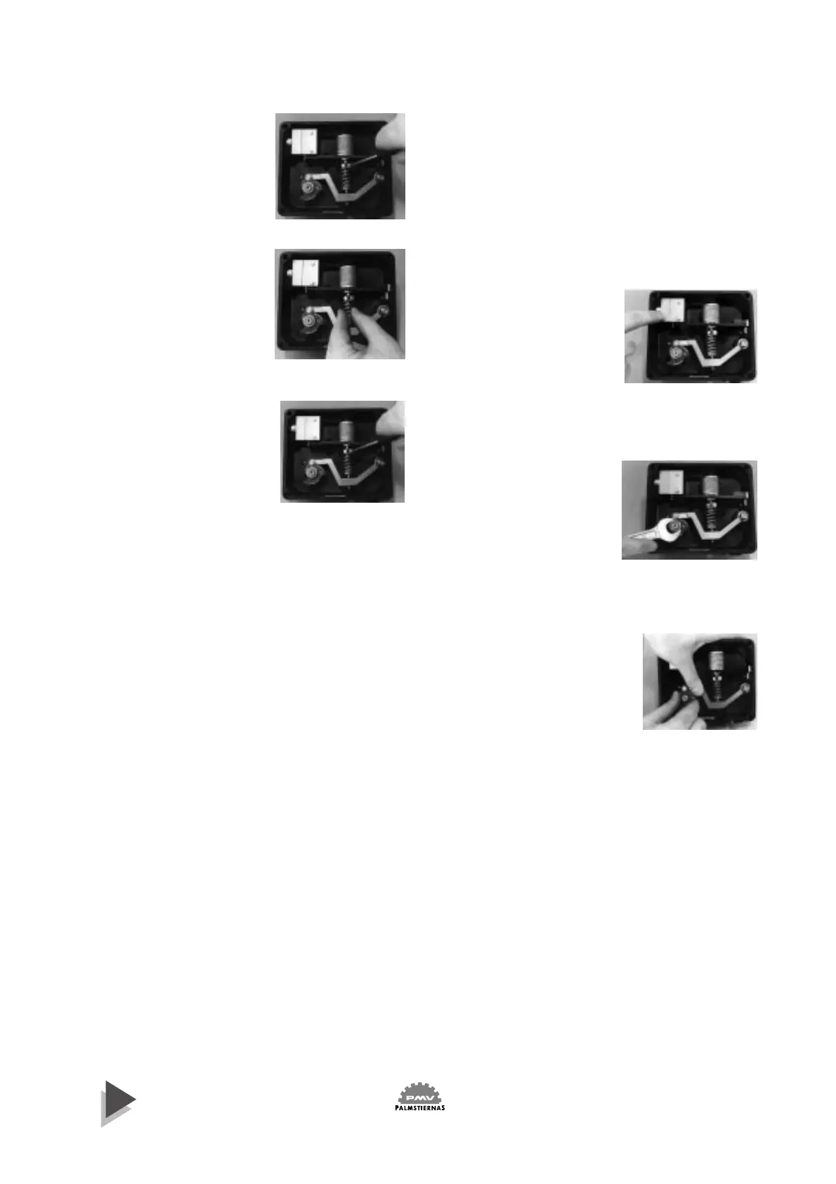
Fig 12
Turn the spring relative to the
nut for less effective spring.
Fig 13
Tighten the screw and make
zero adjustment (make sure
the control pressure signal is
at zero level). Adjust once
more the control pres-sure sig-
nal to top level and check the
movement of the actuator.
Make further adjustments if
necessary.
Fig 14
N.B. After adjustments are
completed please make sure
that screws and are securely
fastened. If these screws are
not accessible, see Section 2.4
below.
3. To change the action
3.1 To change from valve opening
on increasing signal to valve
closing on increasing signal, or
vice- versa, proceed as follows:
Shut off supply and instru-
mental air.
As standard, the positioner is
fitted with an intermediate
piece.
Fig 15
Reverse the flexible tubing
between the positioner ports
Cl and C2.
Remove the positioner cover .
The screws can be left partially
threaded into the cover.
Remove the nut that fastens
the cam to the spindle.
Fig 16
Invert the cam, position it to
the desired signal range,
(stamped on the cam lobes),
and install the nut but do not
tighten the nut yet.
Fig 17
Turn on the supply and in-
strumental air.
Make sure the actuator is in
the position corresponding to
the minimum signal (fully
open for units piped to close
on increasing signal or fully
closed on units piped to open
on increasing signal).
Figure 12
Figure 13
Figure 14
Figure 15
Figure 16
Figure 17
2.4 To turn the top spring guide (18) through 120 degrees
The spring guide can be fitted in three positions in
relation to the balance arm. By compressing the spring,
the spring guide will be released from the balance
arm, and the spring and spring guide can be turned
through 120 degrees in either direction. The spring
guide, nut and spring can thus always be fitted so that
the locking screws and will he accessible.


 To Next Page
 Loading...