– 10 –
Manual P5/EP5 23740/98.10
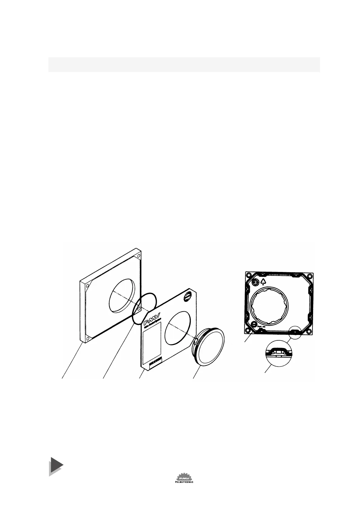
6. Front cover and indicator cover
The front cover of P5 is secured to the pneumatic unit with four
captured screws and sealed with an O-ring 1. The O-ring can be
looped over notches 2 in the front cover to allow for drainage.
There are eight locations on the front cover where the O-ring can be
looped. This O-ring system is common to the Pneumatic unit , I/P unit
and Feedback unit in the PMV Valve Control System P5. This unique
sealing system allows for complete sealing or draining of the units by
changing the position of the O-ring.
The indicator cover 3 is O-ring sealed and secured by a bayonet
coupling. The indicator cover is also used to secure the identification
cover 4.
To remove the indicator cover turn it slightly counterclockwise until it
loosens. Identification cover and O-ring 5 are now removable.
When installing indicator cover and identification cover make sure that
the O-ring is properly engaged.
4315
2
1