PNI Sensor Corporation Doc 1017252 r06
RM3100 & RM2100 Sensor Suite User Manual Page 34 of 41
Where:
STE – Setting this to „1‟ commands the MagI2C to run the built-in self test when
the POLL register is written to. The end of the built-in self test sequence will be
indicated by DRDY going HIGH.
ZOK, YOK, and XOK – These read-only bits indicate whether or not the X, Y,
and Z LR oscillators functioned correctly during the built-in self test. A „1‟
indicates a properly function oscillator. Note that STE also should be HIGH
when this is read, or the reading is invalid.
BW – These two bits define the timeout period for the LR oscillator periods, as
given in Table 5-6.
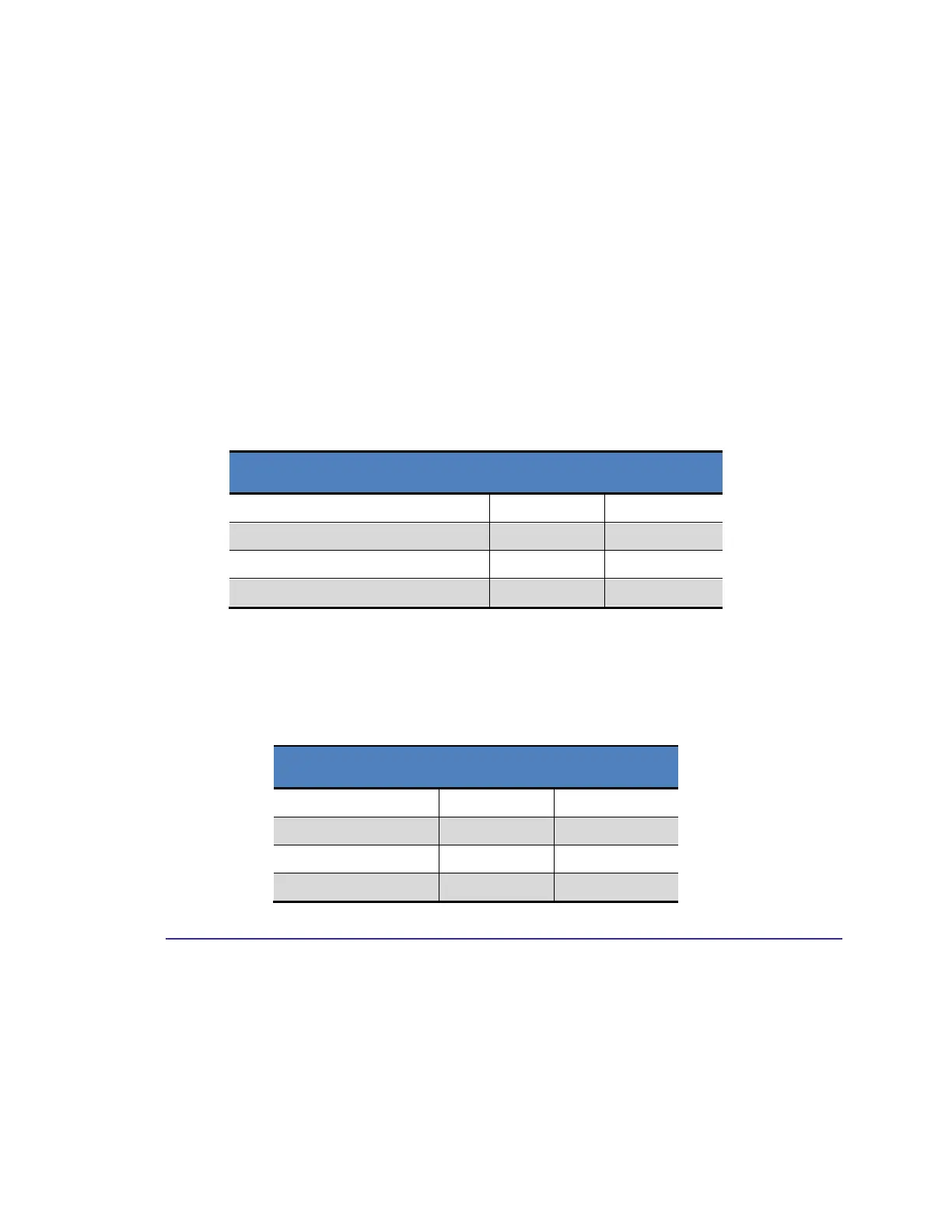
Table 5-6: BIST Timeout Period
1 Sleep Oscillation Cycle (30 µs)
2 Sleep Oscillation Cycles (60 µs)
4 Sleep Oscillation Cycles (120 µs)
BP – These two bits define the number of LR periods for measurement during the
built-in self test, as given in Table 5-7.
Table 5-7: BIST LR Periods
5.6.2 HSHAKE Register (0x35)
The HSHAKE register is used to set conditions for clearing the DRDY pin and for
determining why a register command was not fulfilled. Write to the HSHAKE register
by sending 0x35 followed by the BIST register values, and request a read from the
HSHAKE register by sending 0xB5. The register contents are defined below.


 To Next Page