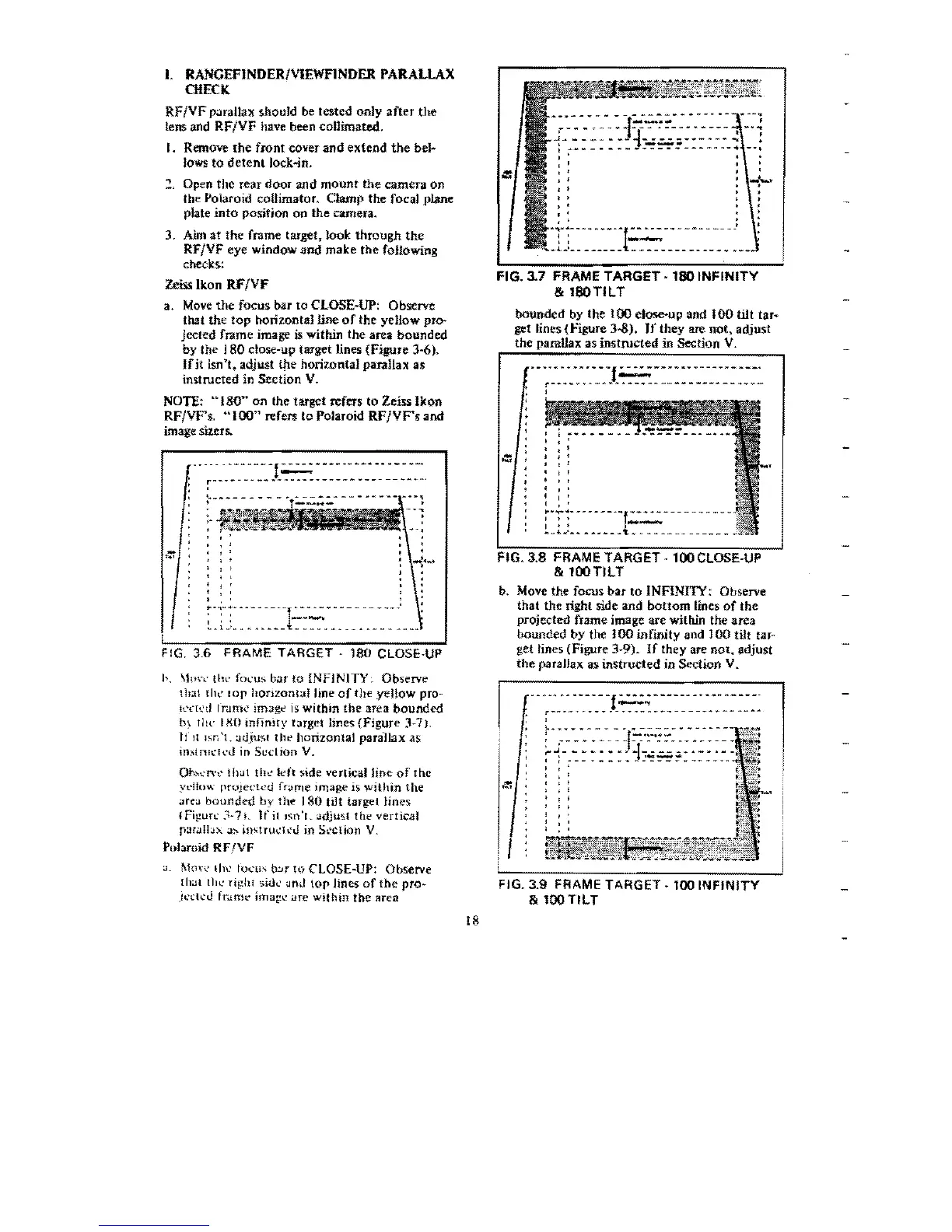
I.
RANGEFINDER/vIEWFINDER PARALLAX
CHECK
RF/VF
p.nailnx
should
be
tested only
after
the
lens
and
RF/VF
have
been
collimated.
I. Remove
the
front cOver
and
extend
the
be}..
Jows
to
detentlock..jn.
"I
Open the rear
door
and
mount
the
camera on
tbe Polaroid collimator. Clamp
the
focal plane
plate
into
position
on
the camera.
3.
Aim at
the
frame target. Jook through
the
RF/VF eye window and make the following
checks:
Zeiss
Ikon
RF
/VF
a.
Move
the
focus bar
to
CLOSE-UP: Observe
that the top horilontalline
of
the yellow pro-
jected frame image is within
the
area bounded
by
the 180 close-up target lines (Figure
3~6).
Ifit
isn't. adjust ttIe horizontal parallax as
instructed in Section V.
NOTE~
"180~'
on
the target refers
to
Zeiss
Ikon
RF/VF'~
"100"
refers to Polaroid
RFIVF',
and
image
mers.
------
---
---
-!
=-
---
--
---
--
-
--
---
r---
- -
--
-~
~
- - -
-- --
-----
~---
--
~---.
,
,
,
,
~-;-;-
-
--
--
---r·
--
----------
--.:
,
. , ,
-~-.-
,
..
__
_
~_l_'_.~
••
______
••
~.
•
____
FIG.
3_6
FRAME TARGET -
180
CLOSE-UP
I,.
\1\1n: illl'
focu:>
bar
to
iNFINITY,
Observe
tll;11
till.'
lOp
hOtlzont"l
line
of
the yellow
pro-
K'ch'd frame jmage
is
within
the
area
bounded
b~
Iltl' I
XO
inflniry
target lines
(Figure
3-7).
If
II
Isn
'1.
adju~t
t hl'
horizontal
paraJlax
as
in~lnl\'"I,,'d
in
Section
V.
Oh"'..'n't'I!l>.l!
Ihl;'
Il;'ft
5lde vertical
hoe
of
the
ydl()w
projected
fr<trne
image is
within
the
"r!;'>.1
bounded
by
Ih
..
180
tilt target
Hnes:
I
Fi!!ur~>
3-7 L
If
it Isn 'r. Jdjus( thl' vertical
p:'lri.llln.,J:'
~!l\fHl\'"ll'U
in
Section
V.
Polaroid
RFfVF
>.I,
[\1,lh'
IITl'
focu\
o:Jr
to
CLOSE-UP:
Observe
{hal lhl.'
ri!,!hf
5idl'
Jnd
top Jines
of
the
pro-
jl>c!CU
fr..tmt' image
are
within
the
area
--~-~-------~-~~-.--
~--
..
-~ ~.
--·~l~":'"':!"-~-~·---
-.~
~-~-~·-1-...;.:..w;;w~-~-.":
:
~.~---------~----
---
..
--,
.
FIG. 3.7 FRAME TARGET
·180
INFINITY
&
I80TILT
bounded
by the
100
close-up
and
100
tilt
ta.r~
get lines
{Figure
J...s).
If
they are not, adjust
the
parallax as
instructed
in
Sectlon
V.
.
----
--
..
--.
-f=-····-
--
----.
-.-.
r--·····--·-··---------------···~
,
,
.'
, ,
, ,
, ,
, ,
,
'
, '
, '
:·T:~
~~~-
--·~f.::.::--
----
---
~_"~'.~
••••
__
ol
••
___________
_
FIG. 3.8 FRAME TARGET -looCLOSE-UP
& 100
TILT
b.
Move
the focus bar
to
INFINITY: Observe
that
the
right
side and
bottom
lines
of
the
projected
frame
image
are
with.in the
area
bounded by the J
00
infmity and
100
tilt tar-
get
lines (Figure
3~9).
If
they are
not,
adjust
the
paraJiax as instructed in Section V.
.---...
----
-
-f
-
--
-
-------
---
--
--
---
,
r---
_
..
--.
-.
-.
-
_.
- ---
---
-
--
--.-
~
-~-
..
-,
!..~~-~---
_.
-------
--.~-
:
.---··----r.:-:·~-·:::"~·-~----
~
J - - • - - - - •
-J-
-----.--
.-
,
._--
,
,-------~-------------
, .
,
,
FIG. 3.9 FRAME TARGET - 100
INFINITY
&
looTlLT
18
 Loading...