Page 1
ID-4 Instant Identification System
The numbers throughout the text refer to the pictures
at the end of this guide.
Introduction
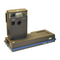
The Polaroid ID-4 System is designed to provide highly secure
photo-identification cards. The system includes a camera, a
laminator and a diecutter. These fit on the base, which
contains the power supply. The base is placed on top of the
cover during operation, or inside for storage.
The camera photographs the subject's face and data card. It
requires a validating signature or seal for additional security.
The ID photograph is inserted into the diecutter and cut to the
appropriate size for the ID card. The laminator seals the diecut
picture into a protective plastic pouch.
The camera uses Polaroid Polacolor ER Type 669 instant film.
Each film pack produces eight 3¼ x 4¼ in. (8.5 x 10.8cm)
prints.
The ID-4 system is available in three basic configurations,
shown on the last page of this guide:
Standard camera Produces two horizontal ID pictures on
each sheet of film.
Vertical-badge camera Produces two vertical ID pictures
on each sheet of film. (These are generally used for
hanging-badge ID cards.)
Single card camera Produces one ID picture on each
sheet of film; these are used for CR-79/CR-80-size ID
cards. This system has a single-card CR-79 or CR-80
diecutter.
Set-up
Select a working area
You will need an area about 8 x 10 ft. (2.4 x 3m) that is not
exposed to extreme temperatures. (Avoid doors, windows,
etc.)
As shown in sketch (1), you also need:
A Table, 29-30 in. (76cm) high, for the ID-4 System.
B Electrical outlet (grounded, where applicable).
C Wastebasket.
D Backdrop to place behind the subject. This should be at
least 30 in. (76cm) square and made of non-reflective
material such as felt or velvet.
E Chair for the subject, 17-18 in. (45cm) high.
Assembly
Assemble the system in the area where you plan to use it.
1 Release the latches, then remove the cover from the base.
Turn the cover upside-down and place it on the table (2).
2 Unwind the power cord. Feed the plug and long cord out
through one of the doors near the bottom of the cover.
Position the short cord in the opening near the top of the
cover (3).
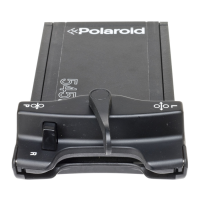
3 Place the base on top of the cover and latch it (4).
4 Place the laminator on the base: slide the bottom of the
laminator into its slot on the base (5), then lower it into
position.
5 Wrap the laminator cord around the bottom of the laminator
several times (6), then plug it into its outlet (7-F).
6 Plug the power cord into its socket (7-G), and then into an
appropriate electrical outlet.
UNIT MUST BE GROUNDED. POWER CORD HAS
THREE-PRONGED GROUNDED PLUG, WHICH MUST BE
PLUGGED INTO APPROPRIATE OUTLET. DO NOT,
UNDER ANY CIRCUMSTANCES, REMOVE GROUND
PRONG FROM PLUG.* DO NOT LET POWER CORD
HANG OVER FRONT EDGE OF TABLE OR COUNTER OR
TOUCH HOT SURFACES. ARRANGE CORD SO IT WILL
NOT BE TRIPPED OVER OR PULLED. IF EXTENSION
CORD IS NEEDED, USE CORD WITH GROUNDED
PLUG* AND SUITABLE POWER RATING. CORDS RATED
FOR LOWER WATTAGE THAN UNIT MAY OVERHEAT.
(*THIS APPLIES ONLY IN COUNTRIES WITH
GROUNDED ELECTRICAL SUPPLIES.)