EasyManua.ls Logo

Pololu Zumo - User Manual

Pololu Zumo
28 pages
Print Icon
To Next Page IconTo Next Page
Loading...
Pololu Zumo Shield for Arduino
User's Guide
1. Overview . . . . . . . . . . . . . . . . . . . . . . . . . . . . . . . . . . . . . . . . . . . . . . . . . . . . 2
1.a. Contacting Pololu . . . . . . . . . . . . . . . . . . . . . . . . . . . . . . . . . . . . . . . . . . . . 3
1.b. Included components . . . . . . . . . . . . . . . . . . . . . . . . . . . . . . . . . . . . . . . . . . 3
2. Assembly . . . . . . . . . . . . . . . . . . . . . . . . . . . . . . . . . . . . . . . . . . . . . . . . . . . . 5
2.a. What you will need . . . . . . . . . . . . . . . . . . . . . . . . . . . . . . . . . . . . . . . . . . . 5
2.b. Assembling the Zumo Shield and chassis . . . . . . . . . . . . . . . . . . . . . . . . . . . . . . . . 5
3. The Zumo Shield in detail . . . . . . . . . . . . . . . . . . . . . . . . . . . . . . . . . . . . . . . . . . . 16
3.a. Features and components . . . . . . . . . . . . . . . . . . . . . . . . . . . . . . . . . . . . . . . . 16
3.b. Front expansion . . . . . . . . . . . . . . . . . . . . . . . . . . . . . . . . . . . . . . . . . . . . . 18
3.c. Jumper settings . . . . . . . . . . . . . . . . . . . . . . . . . . . . . . . . . . . . . . . . . . . . . 19
3.d. 3-axis compass module (accelerometer and magnetometer) . . . . . . . . . . . . . . . . . . . . . . 20
4. Schematic diagrams . . . . . . . . . . . . . . . . . . . . . . . . . . . . . . . . . . . . . . . . . . . . . . 22
5. Arduino pin assignment table . . . . . . . . . . . . . . . . . . . . . . . . . . . . . . . . . . . . . . . . . 23
6. Zumo Shield Arduino Libraries . . . . . . . . . . . . . . . . . . . . . . . . . . . . . . . . . . . . . . . . 24
7. Example project: Border-detecting sumo robot . . . . . . . . . . . . . . . . . . . . . . . . . . . . . . . . 25
7.a. Adding QTR reflectance sensors . . . . . . . . . . . . . . . . . . . . . . . . . . . . . . . . . . . . 25
7.b. Arduino sketch . . . . . . . . . . . . . . . . . . . . . . . . . . . . . . . . . . . . . . . . . . . . . 26
Pololu Zumo Shield for Arduino User's Guide © 2001–2012 Pololu Corporation
http://www.pololu.com/docs/0J57/all Page 1 of 28
Question and Answer IconNeed help?

Do you have a question about the Pololu Zumo and is the answer not in the manual?

Summary

Assembly

2.b. Assembling the Zumo Shield and chassis

Step-by-step guide for physically connecting the shield and chassis.

Motors

Guidance on connecting the Zumo's motors to the shield, including orientation.

Chassis and shield

Instructions for attaching the Zumo Shield and spacer plates to the main chassis.

The Zumo Shield in detail

3.a. Features and components

Overview of the Zumo Shield's main hardware features and their functions.

Arduino pin assignment table

Zumo Shield Arduino Libraries

Example project: Border-detecting sumo robot

7.a. Adding QTR reflectance sensors

Guide on attaching QTR reflectance sensors to detect the edge of a sumo ring.

Overview

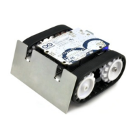
The Pololu Zumo Shield for Arduino is a compact and versatile interface designed to integrate with the Pololu Zumo chassis and an Arduino Uno or Leonardo, creating a low-profile, tracked robot suitable for Mini-Sumo competitions. This shield simplifies the process of building an Arduino-controlled robot by providing essential electronics and additional components for enhanced functionality.

Function Description

The Zumo Shield serves as the central hub for the robot, connecting the Arduino to the Zumo chassis's battery terminals and motors. It provides power regulation for the motors and includes several integrated features to make the robot more interactive and capable.

  • Motor Control: The shield incorporates a DRV8835 dual motor driver, which controls the Zumo's two micro metal gearmotors. This driver utilizes four Arduino pins: two for motor direction (digital pins 7 and 8 for right and left motors, respectively) and two for motor speed control via PWM (digital pins 9 and 10 for right and left motors, respectively). The ZumoMotors library simplifies motor control, allowing for PWM-based speed and direction adjustments and even compensating for accidentally reversed motor connections in software.
  • Power Management: The shield manages power distribution, drawing from the robot's batteries to supply both the motors and the Arduino. It includes a power switch to disconnect motor power (VBAT), which is useful for testing Arduino programs via USB without motor operation. A battery level jumper allows monitoring of the Zumo's battery voltage via Arduino's analog pin 1.
  • User Interface: Two pushbuttons are available on the shield: a reset pushbutton connected to the Arduino's RESET pin, and a user pushbutton connected to digital pin 12. The user pushbutton can be used for various robot interactions, with the Pushbutton library providing debouncing functionality.
  • Sensory Input: The shield features an onboard LSM303DLHC 3-axis accelerometer and compass module. This module provides data that can be used for detecting orientation changes, although its magnetometer readings can be influenced by motor currents, batteries, and external magnetic distortions. Level shifters are built into the shield to ensure compatibility between the 3.3V LSM303DLHC and the Arduino's 5V logic.
  • Auditory Feedback: A buzzer is included for generating sounds and music, which can be used for various purposes, such as audible countdowns in sumo matches. The ZumoBuzzer library facilitates easy control of the buzzer, and it is compatible with melodies written for Orangutan Buzzer functions.
  • Expansion Capabilities: The shield offers front expansion areas with general-purpose I/O pins, allowing for the addition of external sensor modules. These areas include digital and analog pins, as well as I²C SDA and SCL lines, providing flexibility for custom enhancements.

Usage Features

The Zumo Shield is designed for ease of use and integration with the Arduino platform, making it accessible for both beginners and experienced robot builders.

  • Direct Mounting: The shield mounts directly to the Zumo chassis, establishing connections to the battery terminals and motors. The Arduino then plugs into the shield's male header pins, facing down, creating a compact and integrated assembly.
  • Arduino Compatibility: It is compatible with Arduino Uno and Leonardo boards, as well as older Arduinos with the same form factor as the Uno. This broad compatibility allows users to leverage existing Arduino knowledge and resources.
  • Library Support: Pololu provides a suite of Arduino libraries (ZumoMotors, ZumoBuzzer, Pushbutton, and QTR Reflectance Sensors) that simplify programming the robot's various functionalities. These libraries offer high-level functions for motor control, sound generation, pushbutton detection, and reflectance sensor readings, reducing the complexity of writing code from scratch.
  • Example Sketches: The libraries come with example sketches that demonstrate how to use the library functions, providing a starting point for users to understand and implement different robot behaviors.
  • Customization through Jumpers: Several jumpers on the shield allow users to customize connections, such as enabling the buzzer control line (digital pin 3 or 6 depending on the Arduino model) and connecting the battery level monitoring circuit to analog pin 1.
  • Sensor Integration: The front expansion area is specifically designed for integrating reflectance sensors, such as QTR-1RC or QTR-1A, for border detection in sumo competitions or line-following applications. The shield's design allows for mounting two sensors on each side of the front, with options for both analog and digital sensor types.
  • Troubleshooting Guidance: The manual provides specific troubleshooting tips for common issues, such as motors connected backward, incorrect sensor thresholds, or issues with buzzer functionality, guiding users through adjustments to parameters like motor speeds, turn durations, and sensor thresholds.

Maintenance Features

While the Zumo Shield is robust, certain aspects of its assembly and configuration require attention to ensure proper functioning and longevity.

  • Soldering Requirements: Assembly involves soldering various components, including through-hole headers for Arduino connections, pushbuttons, the charge connector, power switch, and battery contacts. Care must be taken during soldering, especially with motor leads and battery contacts, to ensure secure connections.
  • Motor Orientation: Each motor's positive terminal is indicated by a plus sign. Motors should be soldered with the positive terminal closest to the front of the shield. However, if orientation is incorrect, the ZumoMotors library can compensate in software.
  • Spacer Plate Usage: The Zumo Shield assembly utilizes a two-piece acrylic spacer plate, which is included with the shield, instead of the one-piece mounting plate from the Zumo chassis. This design allows for easier disassembly of the Zumo without requiring desoldering of motors or battery terminals.
  • Protective Masking: The acrylic spacer plate pieces come with protective paper masking that can be peeled off for a cleaner look or left on for additional thickness.
  • Mounting Screws: The kit includes two sizes of #2-56 machine screws (1/4" and 5/16"). The longer screws are recommended for the front holes if a sumo blade is being mounted, otherwise, the shorter screws can be used for all four mounting holes.
  • Battery Terminal Soldering: The battery contacts should be soldered to the shield from the top, with the battery terminal slot in the PCB completely filled with solder. Temporary taping or using a battery can help hold the contacts in place during soldering.
  • Shoulder Bolt Tightening: When installing idler sprockets, shoulder bolts should be tightened with a 3 mm hex key until washers are snug against the chassis, but overtightening should be avoided to prevent bending the washers.
  • Disassembly Instructions: The manual provides clear steps for disassembling the robot, including removing tracks, battery cover, batteries, screws, and gently separating the battery terminal spring and motors from the shield, which is useful for maintenance or modifications.
  • I²C Connections for Older Arduinos: For older Arduino Uno R2 or similar boards lacking separate I²C pins, users might need to manually bridge SDA to A4 and SCL to A5 in the front expansion area to use I²C devices.
  • Compass Module Considerations: Users are advised that the magnetometer in the LSM303DLHC is susceptible to interference from motor currents, the buzzer, batteries, and external magnetic fields. While useful for relative orientation changes, achieving accurate absolute heading can be challenging.
  • Power Supply Warning: A critical maintenance note warns against connecting a different power supply to the Arduino's VIN pin or power jack when the Arduino is powered from the Zumo Shield, as this can cause a short and permanently damage both the Arduino and the Zumo Shield.

Pololu Zumo Specifications

General IconGeneral
MicrocontrollerAtmega32U4
Operating Voltage5 V
Motor Channels2
Programming InterfaceUSB
Battery Type4xAA (not included)
SensorsLine sensors, quadrature encoders
CompatibilityArduino
Gear Ratio75:1