Through-hole parts
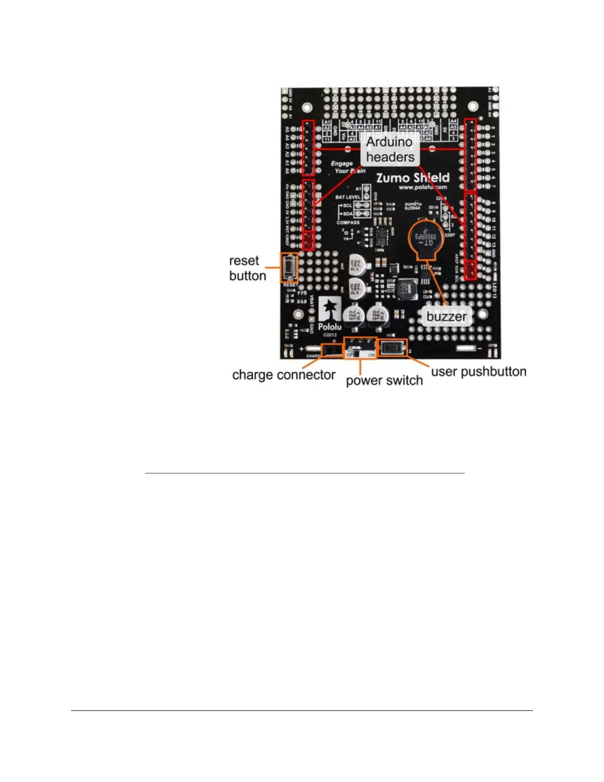
1. Solder the included through-
hole components to the shield:
◦ power switch
◦ reset pushbutton
◦ user pushbutton
◦ buzzer
◦ charging connector
(1×2-pin female header)
2. On the bottom of the board,
trim any leads longer than 1/16″
(the thickness of the spacer plate)
so they do not prevent the shield
from sitting flat on the spacer
plate and chassis.
Arduino headers
3. Separate the 1×40-pin
breakaway male header into the
appropriate segments for
connecting your Arduino and
solder them to the shield. These
header segments should be
soldered to the sets of holes
outlined with white rectangles on
the top of the shield, with the pins facing up.
The newest Arduino boards, including the Uno R3 and the Leonardo, use one 1×10 header, two 1×8 headers, and
one 1×6 header; older Arduino boards use two 1×8 headers and two 1×6 headers (the two pairs of pins highlighted
above in red should not be populated if you are using this board with an older Arduino that does not support these
additional pins). Please make sure you solder the appropriate headers for your particular Arduino!
An easy way to line up the Arduino headers for soldering is to plug them into an Arduino, then place the shield
upside-down on top of them, as shown in the picture below. Be careful to insert the header pins into the correct
set of holes before you begin soldering. Note: if you use this alignment technique, make sure your soldering iron
temperature is not excessively hot and avoid holding the iron on a single pin for more than a few seconds as this
could melt the Arduino’s female headers.
Pololu Zumo Shield for Arduino User's Guide © 2001–2012 Pololu Corporation
2. Assembly Page 6 of 28


 To Next Page