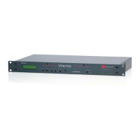
INSTALLATION
VORTEX EF2241 Reference Manual 10 Technical Support: 800.932.2774
• Connect speaker output to loudspeaker.
• If RS-232 remote control is desired, connect the RS-232 R
EMOTE CONTROL port
of the EF2241 to the remote control device, such as an RS-232 interface to a
touch panel or a COM port on a personal computer.
• Connect the L
INE RJ11 jack to an analog telephone line.
• Connect the P
HONE RJ11 jack to an analog telephone set (optional).
• Connect the external power supply to the P
OWER SUPPLY INPUT jack of the
EF2241.
• Set the country code on the EF2241. By default the phone interface will be dis-
abled until you select a country code for the telephony interface. This can either
be done with the front panel LCD menu, or the RS-232 interface. The country
code only needs to be selected the first time or when the country of the installa-
tion is changed.
D
EVICE
ID
S
ON
THE
EF B
US
When considering which Device IDs can be used for which Vortex device, decide
how many devices have the ability to transmit on the W, X, Y, and Z busses, and how
many have the ability to transmit on the P Bus. The EF2280, for example can only
transmit on the W, X, Y, and Z busses while the EF2241 can transmit on the W, X, Y,
and Z busses as well as the P bus. Up to 8 devices can transmit on the W, X, Y, and Z
busses. Similarly, up to 8 devices can transmit on the P bus. Note that the EF2241
counts as one of both types. All devices that can transmit on W, X, Y, and Z must
have unique device IDs. Vortex devices of the same type must have unique device
IDs. If the device IDs of linked Vortex devices are the same, the front panel LCD
screen will display “EFBus Error: Dev. ID Conflict”.
C
ONNECTING
M
ULTIPLE
V
ORTEX
D
EVICES
Up to 8 Vortex devices in combination can be linked together at one time (See Device
IDs on the EF Bus above). Each unit in the chain must have a unique Device ID. Use
the EF Bus to link multiple Vortex devices together.
The following steps should be followed to connect the EF Bus:
1. Set a unique Device ID for each Vortex device. The Device IDs range from 00 to
07.
2. Power off all units.
3. Connect the RS-232 remote control device to any Vortex device in the chain.
4. Connect the provided Cat-5 cable between the EF B
US OUT of the first device,
and the EF B
US IN of the second device.
5. Connect another Cat-5 cable between the EF B
US OUT of the second device and
the EF B
US IN of the third device, and so on.
6. Power on all units at the same time.
Note. The EF Bus must be connected so that the EF Bus In of one
box is connected to the EF Bus Out of another. Connecting
the EF Bus In to another EF Bus In (or Out to Out) will not
work.

 Loading...


