10
Be careful not to drive one Nail on top of another. Damage to the 10.
Nailer might result if this should occur.
Slide the Nailer along the tongue of the board to the location at which 11.
you desire to drive the next nail. (8-10 inches is the general rule of
thumb.) Try to get a nail in each Joist.
Continue Steps 5-10 until you have completely nailed the board.12.
Repeat Steps 4-11 until all but the last Six (6) Rows of boards (or 13.
boards measuring less than 13-1/2” from the wall) have been nailed in
place.
Face Nail the last Six (6) Rows of Flooring or boards measuring less 14.
than 13-1/2” from the wall.
ROUTINE MAINTENANCE / INSPECTION
SCHEDULE
Daily
Inspect the Ram Spring to insure proper return of the Ram.
Inspect the Ram Guide / Ram to insure no dirt or debris is
causing the Ram not to return. Inspect the Driver Blade to
insure there are no chips/dings or rounded-over tip for proper
contact with the nail.
Weekly
Inspect the Pusher End to make sure of proper concise
contact with the nail stack. Inspect the Wear Plate & Shear
Plate to make sure there are no dings to cause improper
contact with or damage to the fl ooring.
Monthly
Inspect the Rail to make sure nails feed into the Shear Plate
/ Wear Plate properly. Inspect the Pawl Spring & the Pawl to
make sure the Tip is not rounded inhibiting ratcheting.
15
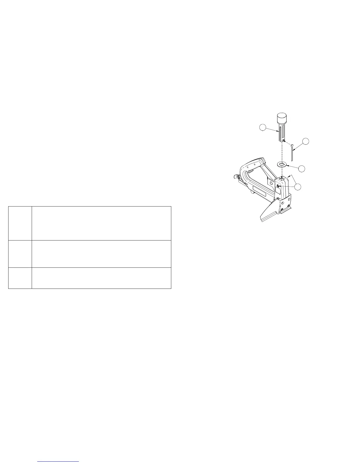
REPLACING THE RAM WASHER
28
24
23
22
Loosen, but DO NOT REMOVE, the two (2) Ram Stop Screws 1.
(Ref. No. 28) while holding the Ram (Ref. No. 22) down.
After the Ram Stop Screws are loose enough to allow the Ram to 2.
be removed, gently pull out the Ram and Driver Blade (Ref. No.
23).
Remove the Driver Blade and slide the worn Ram Washer (Ref. 3.
No. 24) over the Ram to remove it.
Slide the replacement Ram Washer over the Ram until it is 4.
positioned under the Ram Cap.
Reposition the Driver Blade (Ref. No. 23) into the recess in the 5.
Ram (Ref. No. 22). Slip the entire assembly into the Ram Guide
Push the Ram down so the Driver Blade (Ref. No. 23) will slide 6.
down between the Wear Plate and Shear Plate. Hold the Ram
(Ref. No. 22) down and tighten the two (2) Ram Stop Screws (Ref.
No. 28).
 Loading...