6
LOCK MORTISER ASSEMBLY
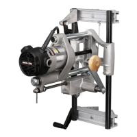
STANDARD EQUIPMENT
With the mortiser, the four sections of the height rod (A), and two bits (B) are
furnished. See Fig. 1.
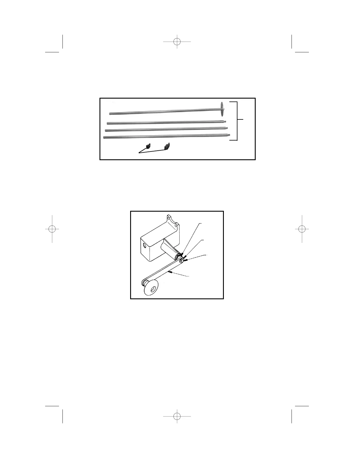
ASSEMBLY OF BASE UNIT
The unit is shipped with the crank handle disassembled.
Place crank handle (D) to crank shaft (A) (See Fig. 2) with wooden knob
facing outward and “D” hole in handle aligned with flat on shaft. Place bolt
(C) through washer (B) and thread into shaft (A). Tighten securely.
ASSEMBLY OF MOTOR UNIT
CAUTION: Disconnect tool from power source.
1. Open hardware package and locate: two cap screws, two flat washers,
and
5
/
32" allen wrench. Place washers onto cap screws.
2. Insert splined cutter shaft (see Fig. 3) through motor carriage (L) and into
the spiral grooved bushing (M) in the main frame (N). Orient motor as shown
in Fig. 8 and seat into motor carriage.
3. Insert the two screw and washer assemblies (from Step 1) through motor
carriage (see Fig. 4) and thread into the threaded holes in motor housing.
Tighten securely with allen wrench.
Fig. 1
A
B
Fig. 2
A
B
C
D