10
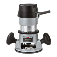
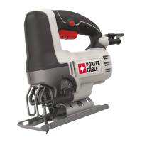
ATTACHING THE MOTOR
1. DISCONNECT
BOTH POWER CORDS (base and
motor) FROM POWER SOURCE.
2. Loosen the clamp screw (A),
Fig. 3 to set the power unit in the
base unit.
3. With the motor switch (C)
positioned (Fig. 3), insert the motor
unit into the base aligning the
lower pin (B) with the groove in the
base.
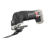
4. Rotate the motor unit into the
base CLOCK-WISE until the motor
switch (C) is opposite the handle
(Fig. 4).
5. Connect the motor unit cord to
the outlet in handle (Fig. 4).
6. Continue rotating the motor
unit into the base until upper guide
pins set rigidly into the base.
7. Tighten clamp screw firmly.
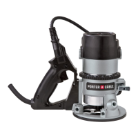
ADJUSTING DEPTH OF CUT
1. DISCONNECT
TOOL FROM POWER SOURCE.
2. Loosen the clamp screw (A),
Fig. 5.
3. Hold the base (E), and turn the
motor unit (F), Fig. 5 COUNTER-
CLOCK-WISE until the tip of the bit
is above the bottom of the base.
4. Set the router on a flat surface.
5. Turn the motor unit (F), Fig. 5
CLOCKWISE until bit touches the
wood surface.
6. Tighten the clamp screw (A),
Fig. 5.
7. Rotate the depth adjusting ring
(B), Fig. 5, until the zero-line (C) is
opposite the index line (D) on the
housing.
8. Loosen the clamp screw (A),
Fig. 5.
9. Tip the router so that the bit is
clear of the wood surface. Turn the
motor unit (F), Fig. 5 CLOCKWISE
until the index line (D) on the motor housing reaches the desired depth
indicated on the ring.
10. Tighten the clamp screw (A), Fig. 5 firmly.
Fig. 3
C
B
A
Fig. 4
C
Fig. 5
F
B
C
D
A
E